Spending years on our production lines perfecting ADSS cable jackets 1 taught us one hard truth: UV and weather damage cause more field failures than most buyers expect.
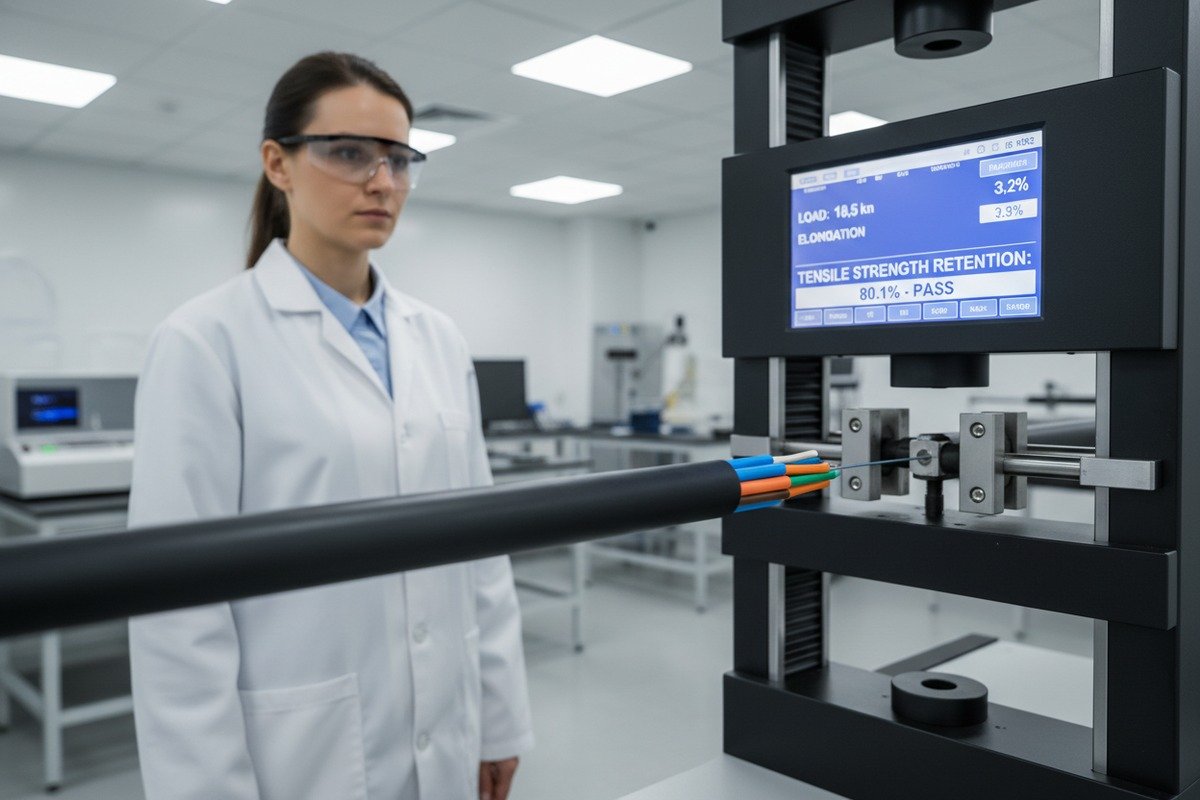
When sourcing ADSS fiber optic cables, prioritize ISO 4892-2/3 for UV resistance, IEC 60794-4-20 for aerial cable weathering, IEEE 1222 for utility-grade performance, and ASTM G154 for accelerated aging. These standards ensure jacket materials retain at least 80% tensile strength after thousands of hours of simulated exposure, protecting your investment for 20–25 years.
This guide breaks down each critical standard, explains what test reports to demand from your supplier, and shows you how to match cable specifications to your local climate AT (anti-tracking) jackets 2. Let's walk through it section by section.
Which international UV resistance standards should I prioritize for my outdoor ADSS cable projects?
Many buyers ask us which UV test certificates actually matter. Not all UV claims are equal, and vague promises of "UV-resistant" jackets have caused costly project failures.
Prioritize ISO 4892-2 (4,000-hour outdoor weatherometer test), ISO 4892-3 (720-hour minimum QUV test), IEC 60794-4-20 (UV-stabilized sheath per method F14), and ASTM G154 (fluorescent UV lamp accelerated weathering). These standards require at least 80% retention of tensile strength and elongation after exposure, ensuring real long-term durability.

Understanding the Core UV Standards
UV degradation 3 is the silent killer of outdoor ADSS cables. Sunlight breaks down polymer chains 4 in jacket materials over time, leading to cracking, brittleness, and ultimately moisture ingress. That is why international standards exist — to simulate years of sun exposure in a controlled lab environment.
ISO 4892-2 is the gold standard for outdoor weatherometer testing. It subjects cable jacket samples to 4,000 hours of cycling — each cycle includes 102 minutes of UV exposure at 60°C followed by 18 minutes of simulated rain at 50°C. That adds up to roughly 2,000 cycles. After this punishing routine, jacket material must retain at least 80% of its original tensile strength and elongation at break.
ISO 4892-3 uses QUV chambers 5 with fluorescent UV lamps. The minimum exposure is 720 hours. This test is faster and cheaper, but it only simulates a fraction of real-world conditions. Some suppliers stop here and call their cable "UV-tested." That should raise a red flag.
IEC 60794-4-20 is specifically written for ADSS and OPGW cables installed along electrical power lines. It mandates UV-stabilized outer sheaths tested per method F14, which includes both UV resistance and tracking/erosion resistance — critical for cables near high-voltage conductors.
ASTM G154 is widely adopted in North America. It uses fluorescent UV lamps to replicate sunlight damage on non-metallic materials. Many U.S. utility companies reference this standard in their procurement specs.
Quick Comparison of UV Standards
| Standard | Test Type | Minimum Duration | Key Requirement | Best For |
|---|---|---|---|---|
| ISO 4892-2 6 | Outdoor weatherometer (UV + rain cycles) | 4,000 hours | ≥80% tensile/elongation retention | Global projects, 25-year life |
| ISO 4892-3 | Indoor QUV chamber | 720 hours | ≥80% tensile/elongation retention | Quick screening, budget projects |
| IEC 60794-4-20 7 | Method F14 UV + tracking | Per IEC spec | UV-stabilized sheath, tracking resistance | Cables near power lines |
| ASTM G154 8 | Fluorescent UV lamps | Varies by cycle | Material degradation assessment | North American utility specs |
| IEEE 1222 | Comprehensive ADSS standard | Referenced tests | Construction, mechanical, environmental | Electric utility power lines |
What to Watch Out For
When our export team reviews RFQs, we often see buyers accept a 720-hour QUV report as sufficient proof of UV durability. That is risky. A 720-hour test simulates roughly 2–3 years of moderate sun exposure — nowhere near the 20–25 years most ADSS installations need to last. Always ask if the supplier has completed the full 4,000-hour ISO 4892-2 test. If they have not, dig deeper.
Also, confirm the test was done on the actual jacket compound used in your cable, not a generic sample from the resin supplier. We test finished jacket material pulled from our extrusion line, because compounding conditions and UV stabilizer dispersion matter enormously.
How can I verify that the jacket material will actually prevent cracking under intense solar exposure?
Our quality engineers have seen cables returned from equatorial installations with jackets that looked decades old after just five years. The root cause? Inadequate UV stabilizer loading in the polyethylene compound.
Verify jacket UV resistance by requesting pre- and post-exposure tensile test data per ISO 4892-2, confirming ≥80% retention. Demand material certificates showing UV stabilizer type and concentration (typically carbon black at 2–3% in HDPE). Ask for third-party lab reports, not just in-house data, and inspect sample jackets for chalking or micro-cracking after aging tests.

The Role of Jacket Material Selection
Not all jacket materials perform equally under intense solar radiation. The two primary sheath types for ADSS cables are PE (polyethylene) and AT (anti-tracking). Each serves a different purpose.
Standard HDPE jackets use carbon black 9 as the primary UV stabilizer. Carbon black absorbs UV radiation before it can reach and break the polymer chains. The typical loading is 2–3% by weight. This works well for most environments.
AT (anti-tracking) jackets are formulated to resist electrical surface tracking — dry-band arcing that occurs when ADSS cables run near high-voltage lines. AT sheaths typically use different fillers and may have slightly different UV performance characteristics. In high-voltage environments (above 33kV), AT jackets are not optional — they are essential.
For harsh climates, our engineering team recommends double-jacket construction: an inner PE layer for moisture barrier and an outer AT layer for UV, abrasion, and tracking resistance. This combination is standard for spans exceeding 200 meters or installations in coastal, tropical, or high-altitude regions.
How to Read a Jacket Test Report
When you receive a test report from a manufacturer, look for these specific data points:
| Data Point | What to Check | Acceptable Range |
|---|---|---|
| Pre-exposure tensile strength | Baseline value in MPa | Per material spec (typically 20–30 MPa for HDPE) |
| Post-exposure tensile strength | After 4,000 hours UV | ≥80% of baseline |
| Pre-exposure elongation at break | Baseline percentage | Typically 300–600% for HDPE |
| Post-exposure elongation at break | After 4,000 hours UV | ≥80% of baseline |
| Carbon black content | Percentage by weight | 2.0–3.0% for UV-grade HDPE |
| Carbon black dispersion | Visual rating per ISO 18553 | Grade 1 or 2 (uniform) |
| Conditioning of control samples | Duration before test | ≥16 hours at standard conditions |
Single Jacket vs. Double Jacket: When Does It Matter?
This is one of the most common sourcing debates. Single jackets cost less and work fine for suburban installations with short spans (under 150 meters) in mild climates. But they are a gamble in challenging environments.
Double jackets add roughly 10–15% to cable cost. However, they extend service life from 10–15 years to 25+ years in harsh conditions. When you factor in the cost of cable replacement — including outage downtime, aerial crew mobilization, and traffic management — the double jacket pays for itself many times over.
We always recommend buyers share their installation location details with us. A cable destined for a rooftop crossing in Minnesota faces very different stresses than one running along a coastal highway in the Philippines. Getting the jacket right from the start eliminates the most common failure mode.
Practical Verification Steps
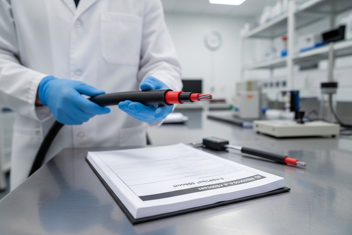
Beyond reading reports, physically inspect samples. Request a 1-meter sample of the cable and a 1-meter sample that has undergone accelerated aging. Compare them side by side. Look for chalking (a white, powdery surface), micro-cracks, or color fading. Bend the aged sample — it should remain flexible, not brittle. This simple hands-on check reveals more than a stack of paperwork.
What specific weather-aging test reports should I request from my manufacturer to ensure long-term durability?
When we prepare documentation packages for overseas utility projects, the test report list often surprises first-time buyers. UV is just one piece of the weather resistance puzzle. Wind, ice, salt spray, moisture, and temperature cycling all attack the cable simultaneously.
Request these specific reports: ISO 4892-2/3 UV aging, IEC 60794-1-22 water penetration and environmental tests, salt fog/spray testing for coastal areas, thermal cycling tests across the full operating range (-40°C to +70°C), tracking and erosion resistance per IEC 60794-4-20, and mechanical load verification including MAT, RTS, and AAS calculations for your exact span and weather conditions.

The Full Weather Resistance Test Portfolio
Weather resistance is not a single test. It is a portfolio of tests that together predict how a cable will perform over decades in real-world conditions. Here is what to request and why each test matters.
IEC 60794-1-22 covers the environmental test methods for optical fiber cables. This includes water penetration testing, tracking and erosion resistance, creep tests, and a range of environmental exposure simulations. This is your baseline document for weather durability.
Salt fog testing (often per IEC 60068-2-11 or ASTM B117) is critical for coastal installations. Salt spray accelerates corrosion of any metallic components and can degrade certain polymer formulations. Even though ADSS cables are all-dielectric, the aramid reinforcement and jacket interfaces still need validation.
Thermal cycling subjects the cable to repeated temperature swings — for example, from -40°C to +70°C — and checks for jacket cracking, fiber attenuation increases, and mechanical degradation. We run these cycles hundreds of times to simulate years of seasonal changes.
The Synergistic Degradation Factor
One of the most underappreciated concepts in cable aging is synergistic degradation. This means that UV, moisture, temperature cycling, and mechanical vibration — when acting together — cause far more damage than any single factor alone. A cable that passes a UV-only test might still fail in the field because wind-induced vibration creates micro-cracks that let moisture in, which then freezes and expands.
This is why multi-factor accelerated aging tests are increasingly important. Progressive manufacturers now run combined exposure protocols that subject cables to UV, humidity, temperature cycling, and mechanical stress simultaneously. If your supplier only provides single-factor test results, ask why.
Key Reports Checklist for Sourcing
| Test Category | Specific Standard/Method | What It Validates | When to Request |
|---|---|---|---|
| UV aging | ISO 4892-2 (4,000 hrs), ISO 4892-3 (720 hrs) | Jacket UV durability, tensile retention | Always |
| Water penetration | IEC 60794-1-22 10 | Moisture blocking effectiveness | Always |
| Salt fog/spray | IEC 60068-2-11 or ASTM B117 | Coastal/saline environment resistance | Coastal or island projects |
| Thermal cycling | IEC 60794-1-22 method | Performance across temperature range | Extreme climate areas |
| Tracking/erosion | IEC 60794-4-20 | Dry-band arcing resistance | Near HV power lines (≥33kV) |
| Mechanical load | MAT/RTS/AAS calculations | Span-specific wind/ice survival | Always (site-specific) |
| Impact resistance | TEC/GR or IEC method | Physical damage tolerance | All aerial installations |
| Vibration/galloping | IEEE 1222 or IEC | Aeolian vibration endurance | High-wind corridors |
| Fiber performance | ITU-T G.652.D or G.657 | Optical attenuation, dispersion | Always |
Red Flags in Test Documentation
Watch for these warning signs when reviewing a supplier's test reports:
- Reports issued by the manufacturer's own lab with no third-party verification.
- Test durations shorter than the standard requires (e.g., 2,000 hours instead of 4,000 for ISO 4892-2).
- Generic material datasheets from resin suppliers instead of tests on finished cable jacket.
- Missing control sample conditioning (samples must be conditioned for at least 16 hours before baseline measurements).
- No fiber attenuation data after environmental cycling.
We routinely invite buyers to witness testing at independent labs. Transparency builds trust and eliminates guesswork.
How do I know if my ADSS cable is designed to survive the extreme temperature fluctuations in my local environment?
Our cables ship to climates ranging from the Saharan heat of North Africa to the frozen winters of northern Russia. Each destination demands different engineering. The wrong thermal specification leads to cracked jackets, increased attenuation, or even structural failure under ice loads.
Verify thermal survivability by confirming the cable's rated operating temperature range (standard: -40°C to +70°C) and installation range (-20°C to +60°C). Request thermal cycling test results, check that MAT and RTS calculations account for your site's worst-case ice and wind loads, and confirm fiber strain stays below 0.05–0.1% across all conditions.

Temperature Ratings: What the Numbers Mean
Every ADSS cable has two critical temperature specifications: the operating range and the installation range. The operating range (-40°C to +70°C for quality cables) defines the temperature extremes the cable can endure once installed and under tension. The installation range (-20°C to +60°C) is narrower because the cable must be handled, pulled, and clamped during installation — processes that impose additional mechanical stress.
If your region regularly hits -30°C in winter or +55°C in summer, you cannot use a cable rated for -20°C to +50°C. This sounds obvious, but we have seen procurement specs that overlook thermal requirements because the buyer focused on optical performance alone.
Mechanical Performance Under Thermal Extremes
Temperature affects more than just the jacket. Cold makes aramid yarn stiffer and can increase cable tension as materials contract. Heat softens the jacket and can increase sag, reducing ground clearance. Both scenarios change the cable's mechanical equilibrium on the span.
Maximum Allowable Tension (MAT) is the highest tension the cable will experience under the worst combination of wind, ice, and temperature in your area. At MAT, fiber strain must stay below 0.05–0.1% with no measurable attenuation increase.
Rated Tensile Strength (RTS) — also called Ultimate Tensile Strength (UTS) — is the breaking point. Your MAT should never approach RTS. Typical design practice keeps MAT at 40–60% of RTS.
Annual Average Stress (AAS) is the long-term average tension the cable lives under. It should be 16–25% of RTS. Exceeding this range accelerates creep and shortens cable life.
Matching Cable to Climate: A Practical Framework
| Climate Type | Typical Extremes | Key Risks | Recommended Specifications |
|---|---|---|---|
| Tropical/Equatorial | +25°C to +55°C, high humidity | UV degradation, moisture, tracking | Double jacket (PE+AT), full UV testing, water blocking |
| Continental/Northern | -40°C to +35°C, heavy ice | Ice load, thermal contraction, galloping | High RTS, aramid reinforcement, ice load ≥500 N/m |
| Coastal | -5°C to +45°C, salt spray | Salt corrosion, tracking, wind | AT jacket, salt fog testing, wind load ≥150 km/h |
| Arid/Desert | -10°C to +70°C, sand abrasion | Extreme heat, UV, abrasion | HDPE outer jacket, full ISO 4892-2, sand abrasion test |
| Mountainous/High altitude | -35°C to +30°C, intense UV | Higher UV irradiance, ice, wind | Double jacket, enhanced UV stabilizers, high MAT |
Ice and Wind Load Calculations
For regions with ice storms, the cable must handle ice loads up to 500 N/m. Wind loads can reach 150 km/h or more depending on the terrain and local weather history. These loads are not theoretical — they represent the worst conditions the cable will face over its 25-year lifespan.
When we prepare a sag-tension calculation for a customer, we need the span length, attachment heights, design wind speed, ice thickness, and temperature extremes. With this data, our engineers calculate the exact MAT, verify fiber strain limits, and confirm that the cable's RTS provides an adequate safety margin.
Spans for ADSS cables typically range from 50 to 1,000 meters, with most practical installations falling between 100 and 300 meters. Longer spans require higher RTS, which means more aramid yarn and heavier cable — increasing weight from roughly 50 kg/km to over 200 kg/km.
Future-Proofing Against Climate Change
Climate variability is no longer a distant concern. Regions that historically never saw ice storms are now experiencing them. Areas with moderate summers are hitting record highs. When we advise buyers, we always recommend specifying for conditions 10–15% beyond current historical extremes. The incremental cost is small compared to premature cable replacement.
Standards bodies are responding to this reality. IEC 60794 updates increasingly incorporate broader temperature and precipitation ranges. Suppliers who stay ahead of these updates — and who can document compliance — offer the best long-term value.
Conclusion
Sourcing ADSS cables that truly survive UV and weather demands more than trusting a label. Request verified ISO, IEC, and IEEE test reports, match jacket and mechanical specs to your exact climate, and partner with manufacturers who prove performance — not just promise it.
Footnotes
1. This page provides a good overview of ADSS fiber optic cables, including their structure and the types of jackets used, such as PE or AT sheaths. ↩︎
2. Explains the specialized function of anti-tracking jackets for high-voltage environments. ↩︎
3. Describes the process by which UV radiation causes material degradation. ↩︎
4. Wikipedia offers a clear and accessible definition of polymer chains, also known as the polymer backbone, which is suitable for a general audience. ↩︎
5. Explains the function and light source used in QUV accelerated weathering chambers. ↩︎
6. Details the scope and method of the ISO 4892-2 standard for material weathering. ↩︎
7. This is the official publication page for IEC 60794-4-20:2018, providing details about the standard for aerial optical cables. ↩︎
8. Outlines the purpose and methodology of ASTM G154 for simulating UV exposure. ↩︎
9. Details the role of carbon black as an effective UV stabilizer in polyethylene materials. ↩︎
10. This is the official publication page for IEC 60794-1-22:2017, detailing environmental test methods for optical fibre cables. ↩︎