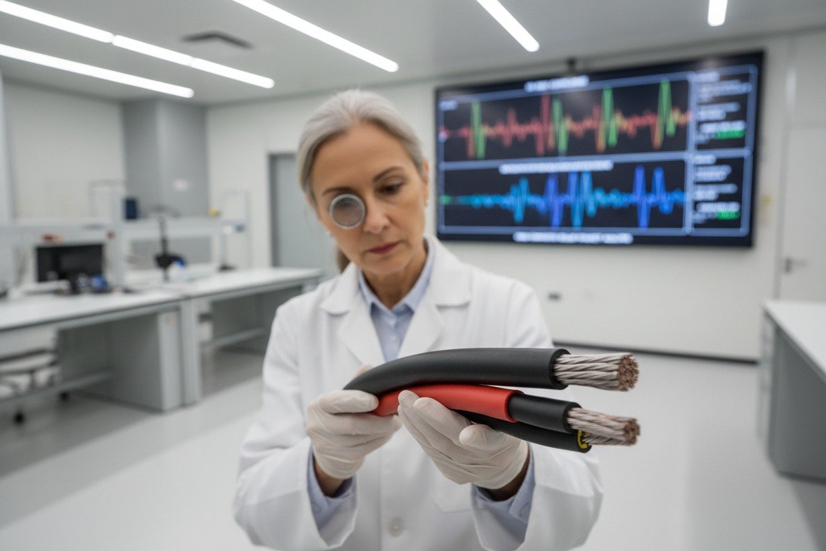
Every year, our quality team reviews dozens of failed cable samples sent back from solar sites worldwide tinned copper conductors 1. The pattern is always the same. Someone picked the wrong cable for the wrong side of the system. A DC-rated cable ends up on an AC run. An undersized conductor melts under load. A cheap jacket cracks after two summers of UV exposure CPR Dca or Cca ratings 2. These failures are not random. They are the direct result of poor cable selection at the design stage. And they cost project owners thousands in downtime, penalties, and replacement labor.
Selecting solar PV cables requires matching distinct specifications to the DC and AC sides of your plant. DC cables like H1Z2Z2-K must handle unidirectional current with enhanced UV and voltage resistance, while AC cables need proper impedance ratings and fire safety compliance for grid connection.
This guide walks you through the exact steps for choosing the right cables on both sides of your solar installation. We cover sizing, certification, fire safety, and UV durability so you can avoid costly mistakes and keep your project on schedule.
How do I choose the right H1Z2Z2-K cable for my DC string connections to ensure maximum efficiency?
Hundreds of cable drums leave our production lines every week bound for solar farms across Europe, Southeast Asia, and Latin America. The H1Z2Z2-K is by far the most requested model. But choosing the right variant is not as simple as picking a cross-section from a catalog.
To choose the right H1Z2Z2-K cable, you must match the conductor cross-section to your string's short-circuit current multiplied by 1.56, verify the voltage rating meets or exceeds system open-circuit voltage, and confirm the cable carries valid TUV 2PfG 1169 certification for outdoor PV use.

Why H1Z2Z2-K Is the Standard for DC Strings
The H1Z2Z2-K cable 3 was designed specifically for photovoltaic systems. Its double-insulated construction uses cross-linked polyolefin (XLPO) material 4. This gives it excellent resistance to UV radiation, ozone, and extreme temperatures ranging from -40°C to +90°C. Unlike general-purpose cables, it is rated for DC voltages up to 1500V DC 5 between conductors, which matches modern high-voltage string designs.
Our engineers always stress one point to buyers: DC systems are typically ungrounded. This means a ground fault on the DC side is far more dangerous than on the AC side. The insulation must be flawless. There is no room for compromise on material quality.
Sizing Your DC String Cable
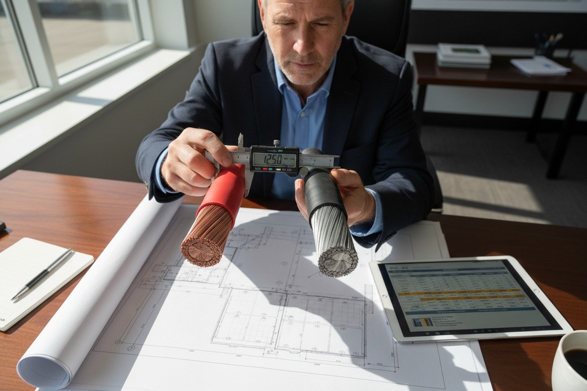
The most critical step is current rating. For cables within the PV array (from panel to combiner box), the rated current must be at least 1.56 times the module's short-circuit current (Isc) 6 at standard test conditions. For cables between the combiner box and the inverter, the minimum is 1.25 times the maximum continuous current.
Here is a quick reference table for common H1Z2Z2-K sizes and their typical applications:
| Cross-Section (mm²) | Max Current Rating (A) | Typical DC Application | Voltage Rating |
|---|---|---|---|
| 4 mm² | 40 A | Single string to combiner box | 1000/1500V DC |
| 6 mm² | 55 A | Parallel strings to combiner box | 1000/1500V DC |
| 10 mm² | 73 A | Combiner box to inverter (small) | 1000/1500V DC |
| 16 mm² | 98 A | Combiner box to inverter (medium) | 1000/1500V DC |
| 25 mm² | 130 A | DC trunk line to central inverter | 1000/1500V DC |
Voltage Drop on the DC Side
Voltage drop must stay below 2% on the DC side. This is non-negotiable. Even a small percentage of additional drop translates directly into lost energy over the system's 25-year life. When our team helps clients with cable sizing, we always calculate voltage drop based on the actual cable run length, not just the electrical rating.
For example, a 30-meter run from a combiner box to an inverter carrying 60A on a 10 mm² copper conductor will produce a voltage drop of roughly 1.03%. That is within the 2% limit. But extend that same run to 60 meters, and the drop doubles. You would need to upsize to 16 mm² or even 25 mm².
Conductor Material Matters
We offer both tinned copper and plain copper conductors. For DC string cables, tinned copper is strongly recommended. The tin coating prevents oxidation at the terminal connections. Over 25 years, untinned copper contacts can develop resistive oxide layers. These create hot spots. Hot spots cause fires. Tinned copper eliminates this risk at a modest cost increase.
Compatibility with Connectors and AFDI
Your H1Z2Z2-K cable must be compatible with MC4 or equivalent PV connectors 7. A mismatch between cable diameter and connector crimping range leads to loose connections. Loose connections cause arcing. Modern systems increasingly require Arc Fault Detection and Interruption (AFDI) devices 8 on the DC side. Your cable choice must support reliable AFDI operation by maintaining clean, low-resistance connections throughout the string.
What are the critical factors I must evaluate when selecting cables for the AC side of my solar plant?
When we ship cables to large EPC contractors in Europe, the AC side specifications often require just as much attention as the DC side. In fact, many project delays we have seen trace back to undersized or incorrectly rated AC cables between the inverter and the grid connection point.
For the AC side, you must evaluate the inverter's maximum output current, apply temperature and installation correction factors to determine the required cross-section, keep voltage drop below 3%, and ensure the cable meets local fire safety classifications such as CPR Dca or Cca ratings.

AC Cable Sizing: Start with the Inverter Output
The inverter output current is your starting point. For a single-phase residential inverter with a maximum output of 27.3A, you cannot simply pick a cable rated for 27.3A. You must apply correction factors.
Temperature correction is the biggest variable. At 45°C ambient temperature, a typical correction factor is 0.79. If the cable runs through a conduit exposed to direct sunlight, you may also need to apply a grouping factor. For a single-phase system, an additional correction factor of 0.85 often applies.
Here is how the math works for a real-world example:
| Parameter | Value |
|---|---|
| Inverter max output current | 27.3 A |
| Temperature correction factor (45°C) | 0.79 |
| Single-phase correction factor | 0.85 |
| Required cable ampacity | 27.3 ÷ (0.79 × 0.85) = 40.6 A |
| Recommended cable size | 6 mm² (rated ~46 A) |
Without these corrections, you might select a 4 mm² cable rated at 36A. That cable would overheat in a hot climate. It would fail within a few years.
Voltage Drop on the AC Side
The AC side allows a slightly higher voltage drop threshold of 3%. But longer cable runs can quickly exceed this limit. A 30-meter run from inverter to grid connection is common. For three-phase commercial systems, runs of 100 meters or more are not unusual.
Voltage drop on AC cables also depends on the cable's impedance and reactance. For larger installations, you cannot ignore reactance. It becomes significant on cables above 50 mm² and on runs longer than 50 meters. Our technical team always recommends calculating both resistive and reactive components for any commercial-scale AC cable run.
Fire Safety and CPR Classification
In Europe, the Construction Products Regulation (CPR) 9 assigns fire safety classes to cables. For solar installations inside or adjacent to buildings, you will typically need at least Dca class. Many large commercial projects and utility-scale farms near populated areas require Cca or even B2ca class.
The CPR class is not just about flame retardancy. It also covers smoke production, flaming droplets, and acidity of smoke gases. Our factory tests every batch for CPR compliance before shipment. We have seen cases where competitors' cables passed initial certification but failed independent batch testing months later. This leads to entire shipments being held at European customs.
| CPR Fire Class | Smoke Class | Application |
|---|---|---|
| Eca | Not classified | Basic indoor, low-risk |
| Dca | s2, d2, a2 | Standard solar installations |
| Cca | s1b, d1, a1 | Commercial/industrial buildings |
| B2ca | s1a, d1, a1 | High-risk public buildings |
Impedance and Reactance for Large Plants
For utility-scale solar farms, the AC cable runs from central inverters to the medium-voltage transformer can be very long. At these distances, cable reactance matters. High reactance causes voltage instability and power factor issues at the point of grid connection. Selecting cables with lower reactance values, or using parallel cable runs, helps maintain stable grid interconnection.
Future-proofing is also important. If you plan to expand your plant or upgrade inverters, choose cables with headroom in both voltage and current ratings. Replacing buried AC cables after installation is extremely expensive.
How can I verify that my solar PV cables meet the strict TUV and CPR fire safety requirements for my project?
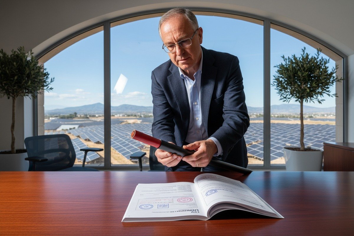
One of the most frequent concerns we hear from procurement managers, especially those sourcing from China for European projects, is certification fraud. They have been burned before. A certificate looked valid. The cable passed initial inspection. But when an independent lab tested a sample from the delivered batch, it failed. The entire shipment was rejected. This is a real and costly problem.
To verify TUV and CPR compliance, you should cross-check certificate numbers directly on the TUV certification body's online database, request third-party batch test reports for every shipment, and insist on cables marked with the correct CPR Declaration of Performance (DoP) number traceable to the manufacturer.

Understanding TUV Certification for Solar Cables
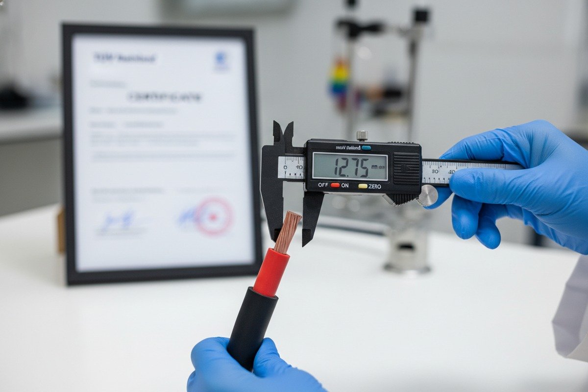
TUV certification for PV cables (commonly referenced as TUV 2PfG 1169 or EN 50618) is not a one-time event. The certification body conducts regular factory audits and periodic sample testing. A valid TUV certificate includes a unique certificate number, the manufacturer's name and factory address, and the specific cable models covered.
Here is what you should check:
-
Certificate number verification. Go to the TUV certifying body's website (e.g., TUV Rheinland or TUV SUD) and enter the certificate number. The database will show you whether the certificate is active, expired, or revoked. It will also list the exact cable types covered.
-
Factory address match. The factory listed on the certificate must match the factory producing your order. Some suppliers hold a certificate for one factory but produce your cables at a different, uncertified facility. Our factory in Hainan is listed directly on all our certificates, and we welcome buyers to verify this at any time.
-
Cable marking consistency. Every meter of certified cable carries a continuous print marking that includes the standard (e.g., EN 50618), the cable designation (e.g., H1Z2Z2-K), the cross-section, and the TUV mark. If the marking is inconsistent, faded, or missing, do not accept the shipment.
CPR Compliance: Beyond the Certificate
CPR compliance requires a Declaration of Performance (DoP) document 10 for every cable type. This DoP references the harmonized European standard (EN 50575) and states the cable's fire classification. The DoP number must be printed on the cable or on its packaging.
Key steps to verify CPR compliance:
- Request the DoP document before placing your order.
- Confirm the DoP references the correct harmonized standard.
- Verify the fire class matches your project requirements (Dca, Cca, etc.).
- Ask for the most recent third-party test report from a notified body.
Independent Batch Testing
The strongest protection against certification fraud is independent batch testing. For every shipment, request that a sample be sent to an accredited European lab (such as KEMA, DEKRA, or Bureau Veritas) for verification. This costs money. But it costs far less than a rejected shipment or a failed grid inspection.
At our facility, we conduct internal testing on every production batch. We also maintain standing agreements with third-party labs to provide rapid turnaround on independent verification reports. This gives our clients documented proof that matches their specific delivered batch, not just a generic certificate from years ago.
Red Flags to Watch For
- Certificates with no verifiable number in the TUV online database.
- Suppliers who refuse to provide DoP documents or batch test reports.
- Cable markings that do not match the certificate details.
- Unusually low prices that suggest inferior raw materials.
- Suppliers who cannot provide a factory audit report from the certifying body.
What steps should I take to ensure my solar cables can withstand extreme UV exposure for over 25 years?
UV degradation is the silent killer of solar cable installations. During our 30 years of manufacturing cable, we have seen returned samples where the outer jacket turned brittle and cracked after just five years. In every case, the root cause was the same: substandard insulation material that was never designed for continuous outdoor UV exposure.
To ensure 25-year UV durability, select cables with cross-linked polyolefin (XLPO) or XLPE insulation specifically tested to EN 50618 or IEC 62930, verify UV aging test reports showing a minimum 720 hours of accelerated weathering, and confirm the jacket uses carbon black or UV stabilizers at the correct concentration.

How UV Degrades Cable Insulation
Ultraviolet radiation breaks down polymer chains in cable insulation. Over time, this makes the material brittle. Cracks form. Moisture enters. Electrical insulation resistance drops. Eventually, the cable fails. In a solar installation, this failure can cause ground faults, arc faults, or even fires.
The rate of degradation depends on three factors: the polymer type, the presence of UV stabilizers, and the intensity of UV exposure at the installation site. A solar farm in the Middle East or sub-Saharan Africa receives far more UV radiation than one in northern Germany. But even in moderate climates, 25 years of continuous exposure will destroy cables made from non-UV-stabilized materials.
Material Selection for UV Resistance
Cross-linked polyolefin (XLPO) is the industry standard for PV cable insulation. The cross-linking process creates chemical bonds between polymer chains. These bonds resist UV breakdown far better than standard PVC or non-cross-linked polyethylene.
Carbon black is the most effective UV stabilizer for cable jackets. It absorbs UV radiation before it can reach the polymer chains. The concentration must be carefully controlled. Too little carbon black provides insufficient protection. Too much makes the material brittle. Our production process maintains carbon black content within the range specified by EN 50618.
For red or blue insulated conductors (where carbon black cannot be used due to color), we use alternative UV stabilizer packages based on hindered amine light stabilizers (HALS). These provide equivalent UV protection without affecting the color.
Accelerated Aging Tests You Should Request
Standard UV aging tests expose cable samples to intense UV radiation in a controlled chamber. The EN 50618 standard requires cables to pass accelerated weathering tests equivalent to decades of real-world exposure. Here is what to look for in test reports:
| Test Parameter | Minimum Requirement | What It Proves |
|---|---|---|
| UV exposure duration | ≥720 hours (accelerated) | Equivalent to 20+ years outdoor |
| Retained tensile strength | ≥50% of original | Jacket remains flexible |
| Retained elongation at break | ≥50% of original | No brittleness or cracking |
| Temperature cycle range | -40°C to +90°C | Survives all climate zones |
| Ozone resistance | Pass (no cracking) | Resists atmospheric degradation |
Installation Practices That Protect Against UV
Even the best cable will degrade faster if installed poorly. Avoid sharp bends that stress the jacket. Use UV-resistant cable ties rated for outdoor use. Standard nylon ties become brittle in sunlight within two to three years. Stainless steel or UV-stabilized polyamide ties last much longer.
Where possible, route cables through cable trays or conduits to reduce direct sun exposure. If cables must be exposed, ensure they are supported at intervals no greater than 600mm as required by NEC and IEC standards. Unsupported cables sag over time. Sagging creates mechanical stress points where UV-weakened insulation is most likely to crack.
Long-Term Inspection and Maintenance
Even with the best cables and installation practices, periodic inspection is essential. We recommend visual inspection of exposed cable runs every two to three years. Look for discoloration, surface cracking, or stiffening of the jacket. Infrared thermography can detect hot spots at connections before they cause failures.
Our recommendation to every project owner is simple: invest in quality cables now, or pay for replacement later. The cost difference between a certified H1Z2Z2-K cable with proven UV performance and a cheap alternative is small compared to the cost of re-cabling a solar farm after 10 years.
Conclusion
Choosing the right solar PV cables for both DC and AC sides demands careful attention to current ratings, voltage drop, certification authenticity, fire safety compliance, and long-term UV resistance. Get these fundamentals right at the design stage, and your solar plant will deliver reliable power for decades.
Footnotes
1. Highlights the benefits of tinned copper conductors, especially corrosion resistance in harsh environments. ↩︎
2. Details the specific fire performance classifications (Dca, Cca) under the Construction Products Regulation. ↩︎
3. Found a comprehensive product page from Lapp, a reputable cable manufacturer, detailing the H1Z2Z2-K solar cable and its compliance with standards like EN 50618. ↩︎
4. Describes XLPO as a cross-linked polyolefin material with excellent properties for cable insulation. ↩︎
5. Explains the advantages and implications of using 1500V DC in solar power plants. ↩︎
6. A working and authoritative page from the original domain, PVeducation.org, defining and explaining short-circuit current (Isc) in solar cells. ↩︎
7. Explains MC4 connectors as standard electrical connectors commonly used for solar panels. ↩︎
8. Describes AFCI/AFDI devices as safety mechanisms to detect and prevent arc faults in PV systems. ↩︎
9. Explains CPR as a regulation for fire safety performance of cables in construction products. ↩︎
10. Found an authoritative government source (Government.nl) providing a clear explanation of the Declaration of Performance (DoP) for construction products. ↩︎