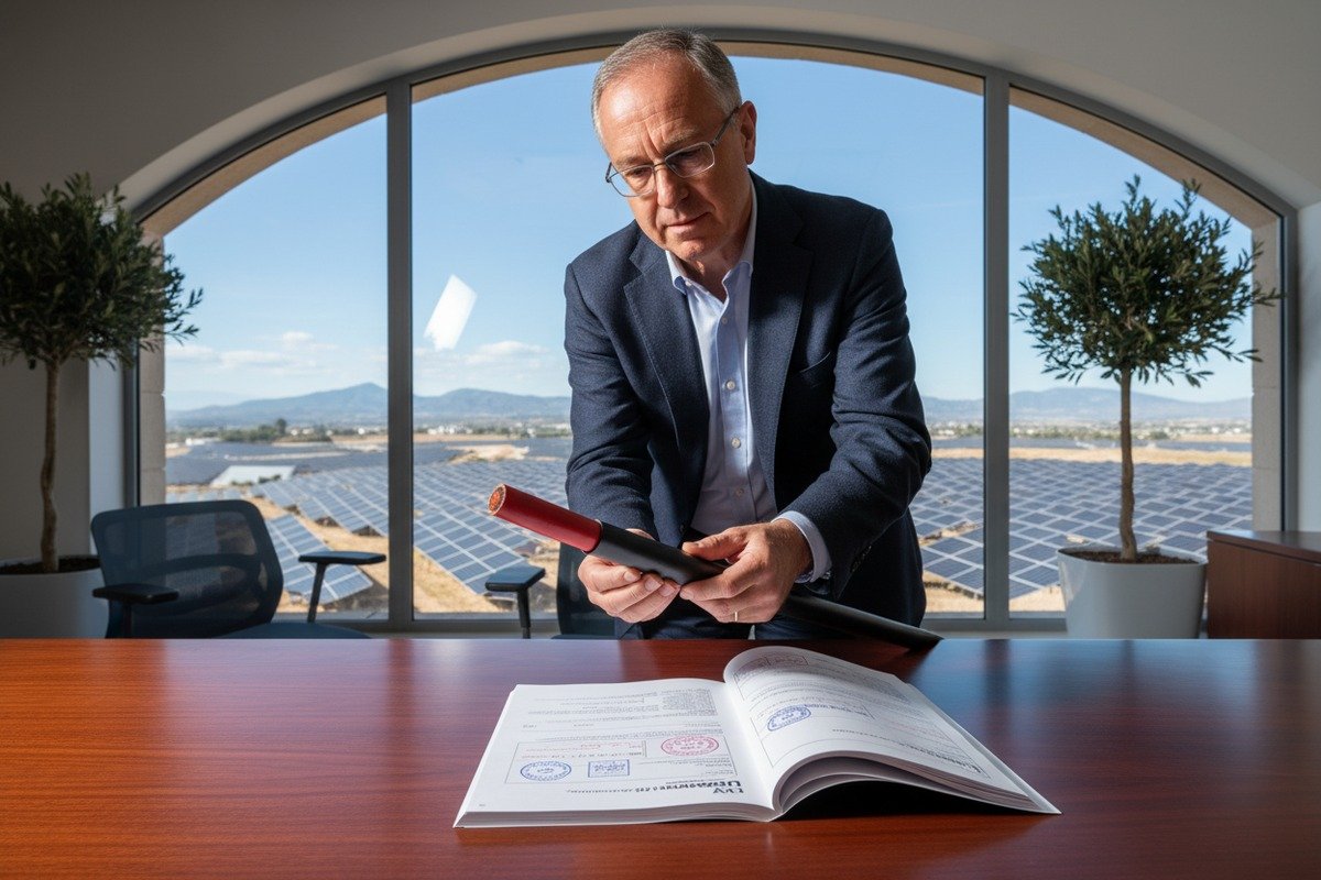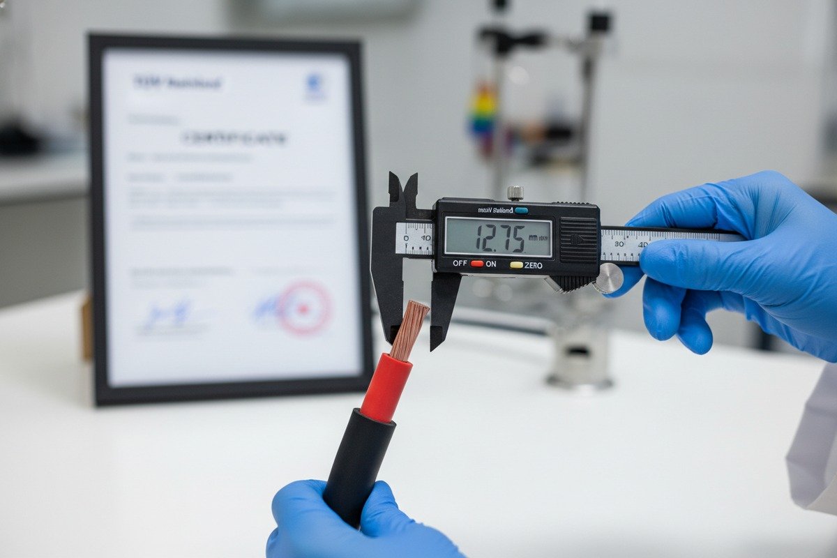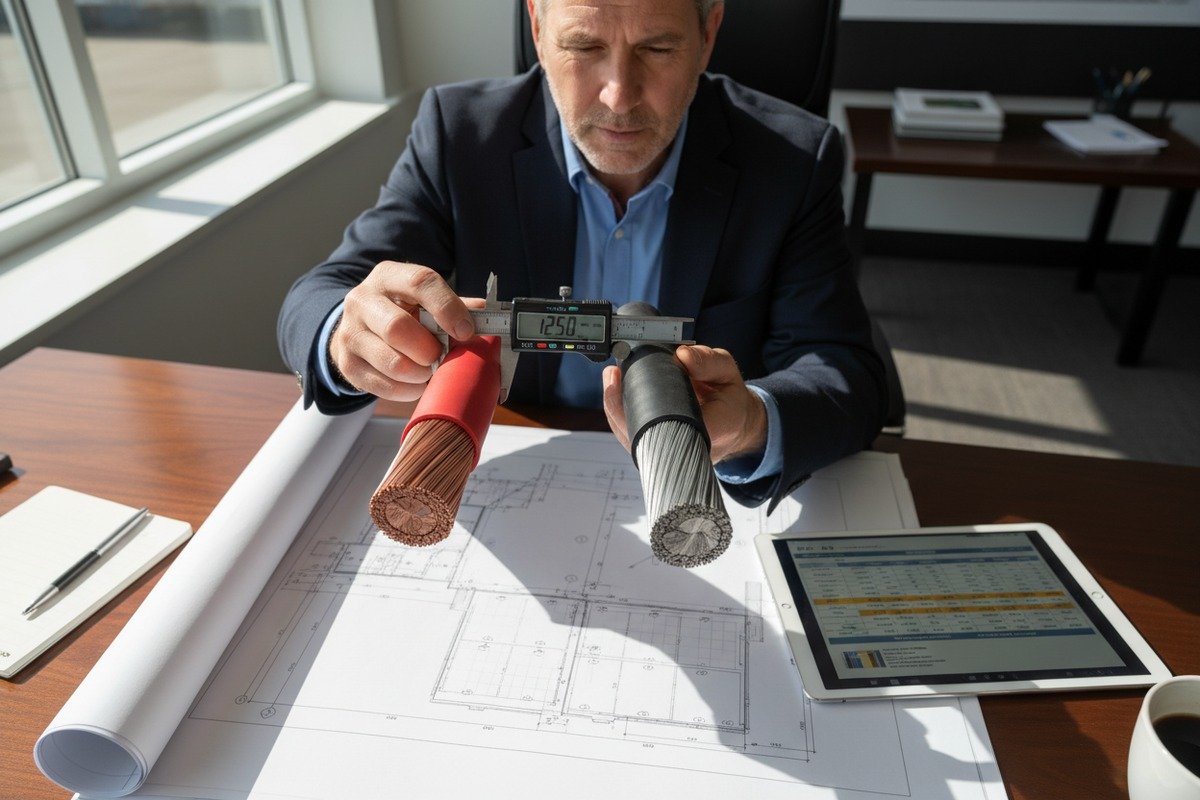
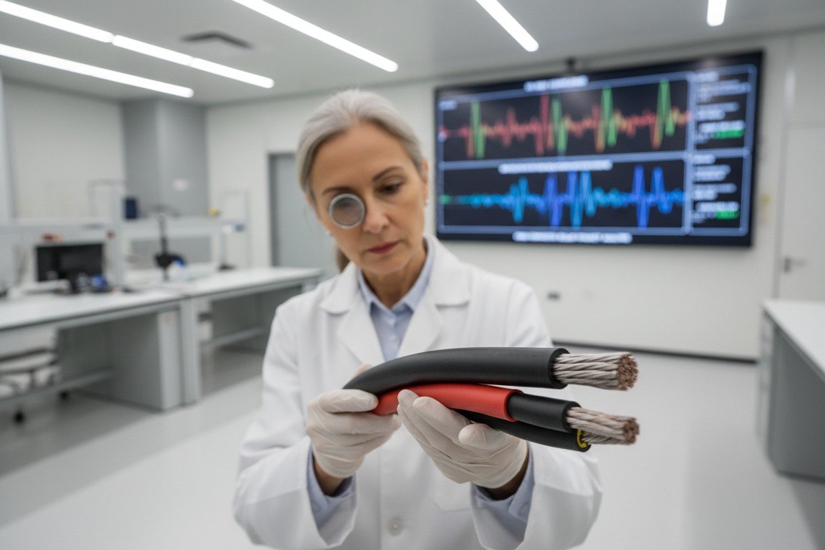
Every year, our production lines push out thousands of kilometers of solar PV cable 1. Yet one question keeps coming back from EPC buyers across Europe and beyond: how do I know these cables won't cause electromagnetic interference problems 2 once they're installed in the field?
To evaluate cable EMC impact on solar PV system performance, you must assess shielding effectiveness, cable inductance and capacitance, compliance with EN 55011, CISPR 22, and IEEE 1547 standards, and demand verified third-party test reports. Poor EMC management in cables leads to inverter instability, signal degradation, and long-term reliability failures.
This guide walks you through exactly what to look for, what to ask your supplier, and how to avoid the costly mistakes we've seen on real projects. Let's break it down step by step.
How do I ensure my solar cables meet the strict EMC standards required for grid-connected EPC projects?
When our engineers audit cables for major European EPC contractors, the first thing they check is not the copper—it's the EMC documentation. Missing or fake compliance paperwork has caused entire shipments to be rejected at customs.
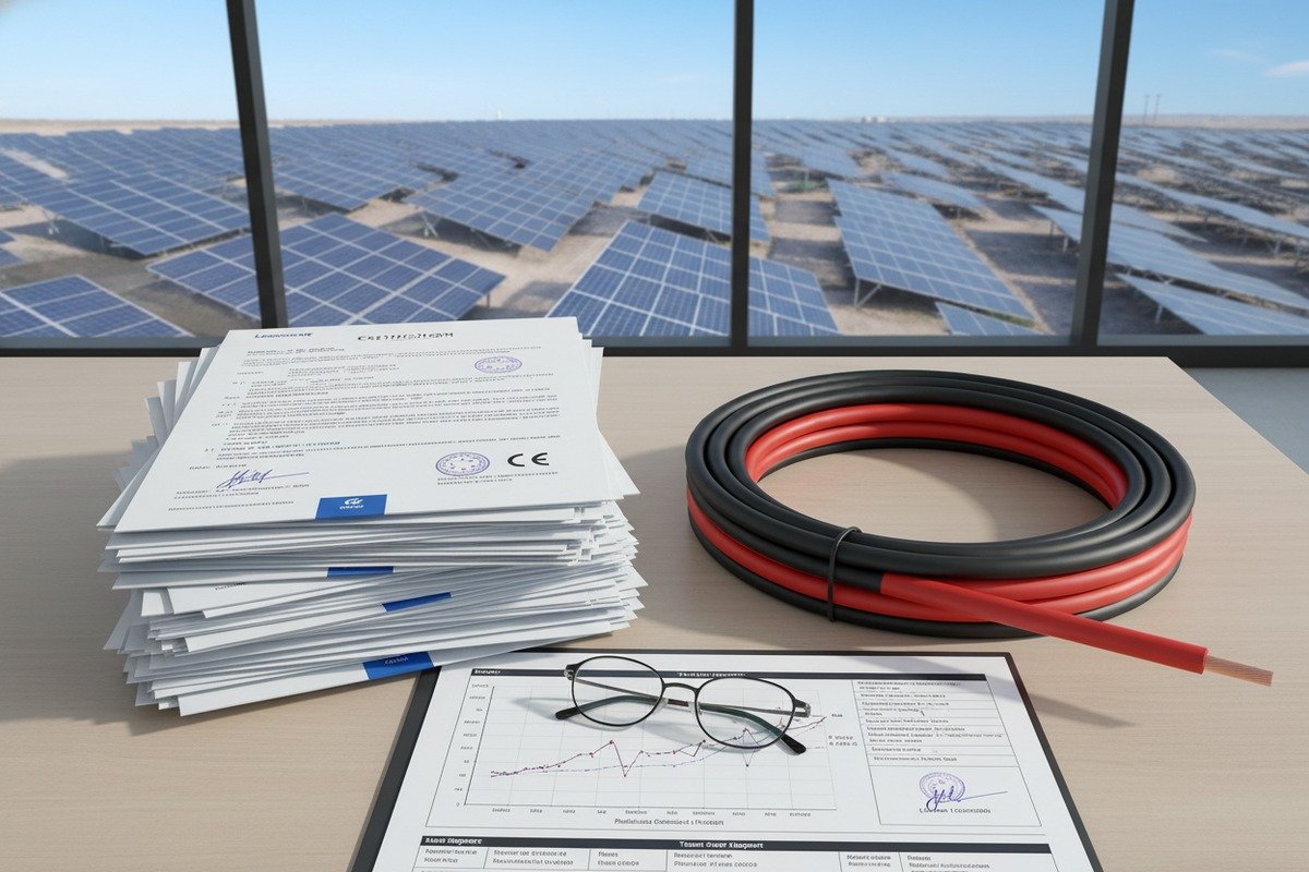
To ensure your solar cables meet strict EMC standards for grid-connected projects, verify compliance with EN 55011, CISPR 22, IEEE 1547, and UL 1741. Demand authentic TUV or CE certificates, request conducted and radiated emission test reports, and confirm that testing was done at cable lengths representative of actual field conditions.
Why Standard Lab Tests Fall Short
Here is a critical gap most buyers overlook. Standard EMC lab tests use short cable samples—often just a few meters long. But on a real solar farm, your DC cable runs stretch tens or even hundreds of meters. At those lengths, the cable's distributed inductance and capacitance 3 create antenna-like behavior. The cable itself becomes a radiator of electromagnetic interference.
A 2014 EU-wide EMC campaign tested 54 solar inverters against EN 55011 4. Only 33% passed. While the blame often falls on the inverter, the DC cabling connected to it plays a major role in amplifying emissions. Resonance effects in long cable runs can push radiated emissions well above the CISPR 22 Class B limit 5 of 40 dBμV/m at 3 meters.
Key EMC Standards You Must Reference
| Standard | Scope | Frequency Range | Relevance to PV Cables |
|---|---|---|---|
| EN 55011 | Conducted & radiated emissions | 150 kHz – 5 MHz (conducted), 30 – 200 MHz (radiated) | Primary benchmark for PV system EMC in Europe |
| CISPR 22 | IT equipment emissions | 150 kHz – 1 GHz | Applied to inverters and connected cabling |
| IEEE 1547 | Grid interconnection | Varies by test | US standard for grid-tied PV systems |
| UL 1741 | Inverter safety & EMC | Varies by test | Mandatory for US market entry |
| EN 61000-6-3/4 | Generic emission/immunity | Broad range | Baseline for residential and industrial environments |
What to Do Before You Place an Order
First, ask your cable supplier for EMC test data that references the actual installation length. If they only have data from a 2-meter sample, that's a red flag. Second, verify that the TUV or CE certificate number can be traced back to the certifying body. We've seen counterfeit certificates in the market. Third, confirm that the cable design includes features like twisted-pair conductors or integrated shielding that reduce antenna effects at field-relevant lengths. When we ship our H1Z2Z2-K cables to European projects, every batch comes with traceable test documentation tied to our TUV certification.
Can I minimize electromagnetic interference in my PV system by selecting high-quality XLPO insulation and shielding?
Over the past 30 years of manufacturing solar cable, our R&D team has tested dozens of insulation compounds. The difference between a generic XLPO and a properly formulated one is not just about heat resistance—it directly affects EMI behavior.
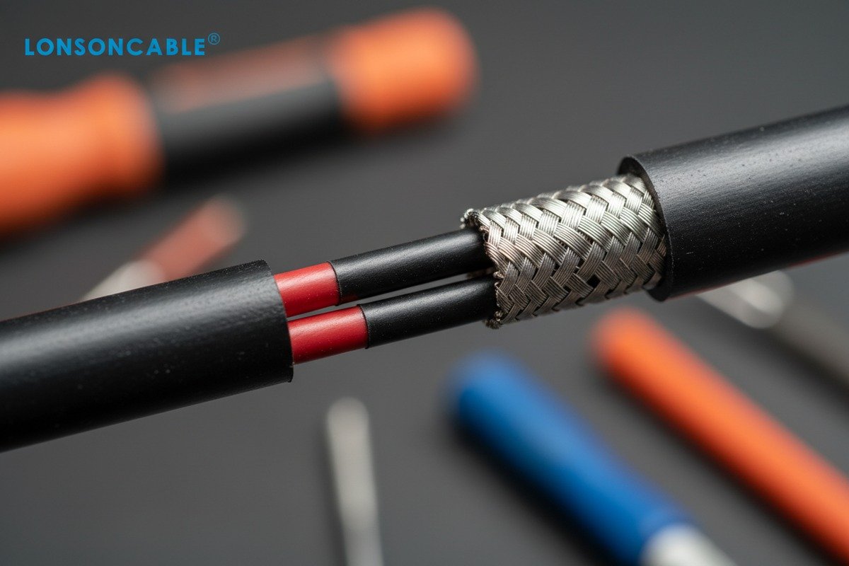
Yes, selecting high-quality XLPO insulation with low dielectric constant and proper shielding significantly reduces electromagnetic interference. Quality XLPO minimizes parasitic capacitance, while braided or foil shielding contains radiated emissions. Combined, they lower both common-mode and differential-mode noise propagation through your PV cable runs.
How Insulation Material Affects EMI
The dielectric constant 6 of your cable's insulation directly determines its parasitic capacitance. Higher parasitic capacitance means more energy is stored and released as high-frequency noise. XLPO (cross-linked polyolefin) 7 is favored in solar cables because it offers a lower dielectric constant compared to standard PVC, which means less capacitive coupling between conductors and between the conductor and ground.
But not all XLPO is created equal. Cheap formulations use fillers that raise the dielectric constant or degrade under UV exposure, changing the cable's electrical characteristics over time. When we formulate our XLPO compounds at our 230,000 m² facility, we control the filler ratios precisely to maintain stable dielectric properties across a 25-year lifespan.
Shielding Options and Their EMC Effectiveness
| Shielding Type | EMI Attenuation | Cost Impact | Best Use Case |
|---|---|---|---|
| No shielding | None | Lowest | Short runs with no sensitive equipment nearby |
| Aluminum foil wrap | Moderate (good for high-frequency) | Low-medium | Standard residential and small commercial installs |
| Braided copper shield | High (broadband) | Medium-high | Utility-scale farms near communication equipment |
| Foil + braid combination | Very high | Highest | Dense arrays, sites with strict radiated emission limits |
The Common-Mode vs. Differential-Mode Problem
EMI in PV systems travels in two ways. Differential-mode noise flows between the positive and negative conductors. Common-mode noise flows between the conductors and ground. Shielding primarily addresses common-mode noise by providing a low-impedance path to ground. But you also need to consider conductor geometry. Keeping the positive and negative conductors close together—or better yet, twisted—cancels out some differential-mode emissions.
Our engineers often advise EPC contractors to pair shielded cables with proper grounding at both the inverter and combiner box ends. Without correct grounding, a shield is just an expensive layer of metal that does nothing. In fact, an improperly grounded shield can actually increase EMI by creating ground loops.
Don't Forget Environmental Degradation
High-quality XLPO also resists UV degradation, ozone attack, and thermal cycling. When insulation degrades, micro-cracks form. These cracks change the cable's impedance profile, creating impedance mismatches that generate standing waves and reflections. Over time, what started as a perfectly EMC-compliant cable becomes a source of interference. This is why we stress the importance of sourcing cables with verified UV resistance ratings—not just for mechanical longevity, but for sustained EMC performance.
What specific test reports should I demand from my supplier to verify EMC compliance and prevent system failures?
When our sales team sits down with a procurement director from a European EPC firm, the conversation almost always turns to paperwork. Not just any paperwork—the right paperwork. Incomplete or irrelevant test reports are one of the biggest risks in international solar cable sourcing.
You should demand conducted emission tests (150 kHz–5 MHz), radiated emission tests (30–200 MHz), electrostatic discharge (ESD) immunity reports, electrical fast transient (EFT) burst tests, voltage dip/interruption immunity data, and magnetic field immunity results. All tests should reference EN 61000-series standards and include cable length specifications matching your installation.
The Complete Test Report Checklist
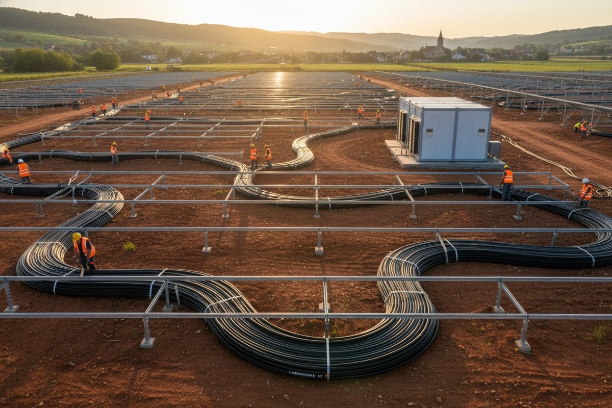
Here is exactly what you should request from any supplier before signing a purchase order. Each test serves a specific purpose, and skipping even one can leave a gap that leads to system failure in the field.
| Test Type | Standard Reference | What It Verifies | Why It Matters |
|---|---|---|---|
| Conducted emissions | EN 55011 / CISPR 22 | Noise on power lines (150 kHz–5 MHz) | Prevents interference fed back into the grid |
| Radiated emissions | EN 55011 / CISPR 22 | Electromagnetic radiation (30–200 MHz) | Stops cables from disrupting nearby equipment |
| ESD immunity | EN 61000-4-2 | Resistance to static discharge | Protects against installer-caused damage |
| EFT/Burst immunity | EN 61000-4-4 | Tolerance to fast transient pulses | Simulates switching surges in the system |
| Voltage dip immunity | EN 61000-4-11 | Performance during grid sags | Ensures stable operation during grid events |
| Magnetic field immunity | EN 61000-4-8 | Resistance to external magnetic fields | Critical for sites near transformers or power lines |
| Surge immunity | EN 61000-4-5 | Lightning and switching surge tolerance | Protects against indirect lightning strikes |
How to Spot a Fake or Incomplete Report
We've encountered situations where suppliers present test reports that look official but fail under scrutiny. Here are the warning signs. The report does not list the cable length used during testing. The testing lab is not accredited by a recognized body like ILAC or DAkkS. The certificate number cannot be verified on the certifying organization's website. The report is older than five years, and the product design has changed since then.
Ask for Length-Specific Data
This point deserves special emphasis. A test performed on a 1.5-meter cable sample tells you almost nothing about how that cable will behave at 80 meters. At our facility, when we prepare documentation for utility-scale projects, we include supplemental data showing how impedance and emission characteristics scale with length. If your supplier cannot provide this, consider it a significant gap in their quality assurance process.
Third-Party vs. In-House Testing
Always prioritize third-party test reports 8 from accredited laboratories. In-house testing is useful for process control, but it carries an inherent conflict of interest. A reputable supplier will not hesitate to share independent lab results. When buyers visit our factory in Hainan, we walk them through every certificate, every test log, and every traceability record. Transparency is not optional—it's the foundation of trust in this industry.
How will the EMC characteristics of my chosen PV cables impact the long-term reliability and signal integrity of my solar farm?
Throughout our three decades of cable manufacturing, we've tracked field performance data from projects across four continents. The pattern is clear: cables with poor EMC characteristics don't just cause interference today—they create compounding problems that worsen every year.
Poor cable EMC characteristics degrade long-term solar farm reliability by disrupting MPPT tracking accuracy, causing voltage fluctuations, accelerating insulation aging from high-frequency stress, and creating impedance mismatches that reduce power output. Over 25 years, these effects compound into significant energy yield losses and increased maintenance costs.
MPPT Tracking and Power Output Loss
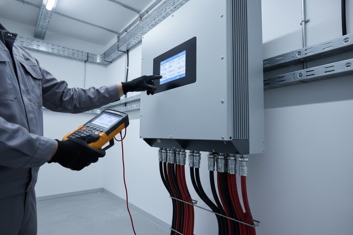
Maximum Power Point Tracking (MPPT) 9 is the algorithm your inverter uses to extract the most energy from your panels. It relies on clean voltage and current signals from the DC side. When EMI corrupts these signals, the MPPT algorithm hunts—oscillating back and forth instead of locking onto the true maximum power point. This hunting behavior can reduce energy harvest by 2–5% on an ongoing basis. On a 100 MW farm, that translates to millions of dollars in lost revenue over the project's lifetime.
Impedance Mismatches and Standing Waves
When the impedance of your PV cable does not match the impedance of the modules or the inverter input, signal reflections occur. These reflections create standing waves at specific frequencies. At resonant points, the voltage or current can spike well above normal levels. This stresses both the cable insulation and the connected electronics. Over years of operation, these repeated micro-stresses fatigue the insulation, leading to partial discharge and eventually insulation breakdown.
The Insulation Aging Feedback Loop
High-frequency EMI does more than cause immediate interference. It creates localized heating within the insulation material through dielectric losses. This heating accelerates chemical degradation of the XLPO. As the insulation degrades, its dielectric properties change—parasitic capacitance increases, impedance shifts, and the cable becomes an even worse EMI emitter. It's a vicious cycle. The only way to break it is to start with cables that have genuinely high-quality insulation and proper shielding from day one.
Grounding and Cable Management for Longevity
Proper grounding is not a one-time installation task. Grounding connections corrode over time, especially in coastal or industrial environments. When a ground connection degrades, the shield effectiveness drops. Our recommendation to every EPC contractor we work with: specify maintenance intervals for grounding inspections in the O&M contract. Use corrosion-resistant hardware. Route cables in conduit where possible to add a secondary layer of EMI protection and physical protection against rodents and UV.
Real-World Cost of Ignoring Cable EMC
Consider a scenario we've seen on multiple projects. A farm uses unshielded cables to save on upfront costs. Within three years, the inverters start showing unexplained fault codes. The MPPT efficiency drops. A technician is called out. After weeks of diagnosis, the root cause is traced to cable-generated EMI. Replacing cables on an operational solar farm is extraordinarily expensive—easily ten times the cost difference between shielded and unshielded cable at the time of original installation. The lesson is simple: invest in EMC performance upfront, or pay far more later.
Planning for 25-Year EMC Stability
When we design cables for long-life projects, we consider every factor that could change the cable's electromagnetic behavior over time. UV exposure, thermal cycling, mechanical stress from wind vibration, and moisture ingress all play a role. Our EN 50618 10 and H1Z2Z2-K cables are formulated and tested to maintain stable dielectric and impedance characteristics across their full rated lifespan. That stability is what separates a cable that merely works on day one from a cable that delivers consistent performance for 25 years.
Conclusion
Evaluating cable EMC impact is not optional—it's essential for protecting your solar investment. Choose cables with verified shielding, quality XLPO insulation, and traceable third-party EMC test data. Your system's long-term performance depends on it.
Footnotes
1. Explains what PV cables are and their specific requirements for solar systems. ↩︎
2. Provides a clear, authoritative definition of electromagnetic interference. ↩︎
3. Explains the concept of distributed inductance and capacitance in transmission lines. ↩︎
4. Reference 3. ↩︎
5. Explains CISPR 22 Class B limits for radiated and conducted emissions. ↩︎
6. Provides a physics-based explanation of the dielectric constant and its effects. ↩︎
7. Defines XLPO and its properties as a cable insulation material. ↩︎
8. Explains the importance and credibility of independent third-party test reports. ↩︎
9. Explains the fundamental concept and application of Maximum Power Point Tracking in solar systems. ↩︎
10. Outlines the specifications for electric cables used in photovoltaic systems. ↩︎