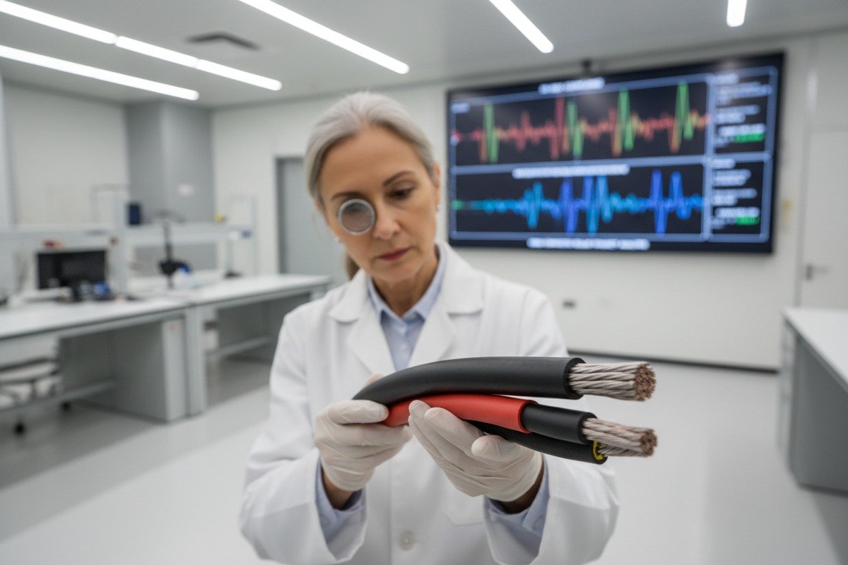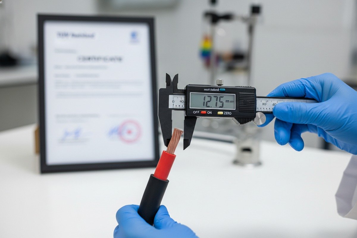
Every year, our production team reviews field failure reports from EPC partners across Europe and the Middle East. One pattern keeps showing up: cables that passed basic electrical tests but snapped or cracked during installation pulling. The damage was invisible at first—micro-tears in the insulation, stretched conductors—but months later, these hidden wounds caused insulation resistance drops, hot spots, and even arc faults. The cost of replacing buried or rooftop cables after commissioning is brutal. It can delay grid connection by weeks and trigger six-figure penalty clauses. This is a problem that starts long before the cable reaches the jobsite. It starts in the factory and in the test lab.
To verify solar PV cable mechanical strength for installation pulling force, request third-party tensile test reports per IEC 62930 or EN 50618, confirm the cable's rated break force exceeds four times your calculated maximum pulling tension, and validate that elongation at break meets minimum thresholds for both conductor and insulation materials.
This guide walks you through every step—from reading test certificates to calculating safe pull limits on site. Let's start with the fundamentals of tensile strength 1 verification.
How can I verify the tensile strength of my solar cables to ensure they survive high-stress installation?
When we ship H1Z2Z2-K cables to large solar farms in southern Spain or the Philippines, our clients often ask one direct question: "How do I know this cable won't break when my crew pulls it through 50 meters of conduit?" It is a fair question. The answer lies in tensile testing data—and knowing how to read it.
You verify tensile strength by reviewing certified test reports that show the cable's break force (in Newtons), elongation at break (as a percentage), and post-aging retention values, then comparing these figures against the pulling forces your installation method will generate.
What Tensile Testing Actually Measures
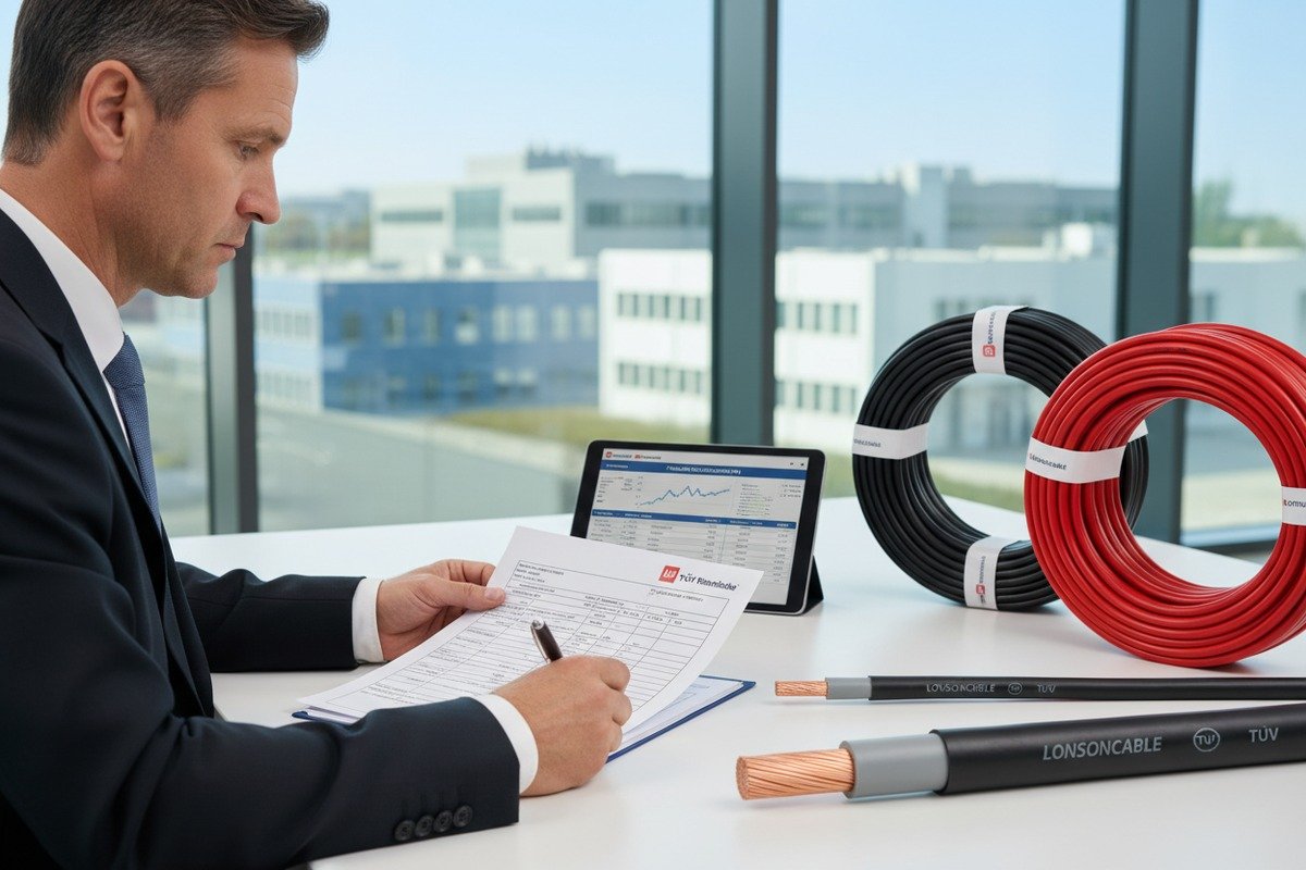
Tensile testing is straightforward. A lab clamps a cable sample—typically 100 to 250 mm long—into a universal testing machine 2. The machine pulls at a constant speed, usually 100 to 500 mm per minute. Sensors record the force applied and the sample's elongation in real time. The test continues until the sample breaks.
Two numbers matter most. First, the tensile strength at break—the maximum force per unit area the material can handle before it snaps. For copper conductors used in solar cables, this is typically above 200 N/mm². For XLPO or XLPE insulation 3, the benchmark is 10 to 20 MPa. Second, elongation at break tells you how much the material stretched before failing. Higher elongation means the cable can absorb more pulling energy without cracking. If elongation at break is below 125% for insulation, the cable is too brittle for field use.
How to Read a Tensile Test Certificate
When you receive a test report, look for these specific data points:
| Parameter | What It Tells You | Minimum Benchmark |
|---|---|---|
| Conductor tensile strength | Force needed to break the copper or aluminum core | ≥ 200 N/mm² (annealed copper) |
| Insulation tensile strength | Force needed to break the jacket material | ≥ 10 MPa (XLPO/XLPE) |
| Elongation at break (insulation) | How far insulation stretches before cracking | ≥ 125% |
| Post-aging tensile retention | Strength remaining after accelerated heat aging | ≥ 70% of original value |
| Sample condition | Whether tested before or after UV/thermal aging | Both pre- and post-aging required |
A certificate missing post-aging data is a red flag. Our quality control team runs both virgin and aged samples because real-world cables face years of UV, heat, and mechanical stress. A cable that tests well fresh but degrades after aging will fail in the field.
Practical Steps for Verification
First, always request the original third-party lab report—not a summary sheet. Second, cross-check the test standard cited (IEC 62930 4, EN 50618, or UL 4703) against your project's regional requirements. Third, confirm the cable model and batch number on the report match what you are purchasing. We have seen cases where suppliers provide valid certificates for a different product line. Finally, if you are pulling cables through long conduit runs or complex trays, ask the manufacturer for the cable's rated maximum pulling force in Newtons—not just the material tensile strength.
Which TUV or UL test reports should I request to confirm the mechanical load limits of my PV cables?
During our regular audits with TÜV Rheinland and UL inspectors at our Hainan facility, we have learned exactly which test documents carry weight—and which ones are just marketing fluff. Many buyers receive glossy compliance certificates but never see the raw mechanical test data underneath. That gap can be expensive.
Request the full TÜV test report per EN 50618 or TUV 2PfG 1169, or the UL 4703 test report, specifically including mechanical test sections for tensile strength, elongation at break, bending, cold bend, and impact resistance—not just the summary compliance certificate.

Understanding the Key Standards
Three main standards govern solar PV cable mechanical testing globally. Each one has a different scope and focus.
EN 50618 is the European harmonized standard. It covers single-core cables for photovoltaic systems rated 1.5 kV DC. Its mechanical tests include tensile strength and elongation for both conductor and insulation, cold bend at -40°C, and resistance to mechanical shock.
TUV 2PfG 1169 is a TÜV-specific product standard that predates EN 50618. Many legacy cables still carry this certification. Its mechanical requirements are similar but not identical. If your project specification calls for EN 50618 compliance, a 2PfG 1169 report alone may not satisfy the authority having jurisdiction.
UL 4703 6 is the North American standard for photovoltaic wire. It includes a different set of mechanical tests—crush resistance, cold bend, and cable marking durability—alongside tensile requirements. If you export to the US, Canada, or markets that reference NEC Article 690 7, this is your baseline.
Which Sections of the Report Matter Most
| Standard | Key Mechanical Test Sections | What to Look For |
|---|---|---|
| EN 50618 | Clause 5.2 (Tensile), Clause 5.3 (Elongation), Clause 5.8 (Bending) | Break force ≥ standard minimum; elongation ≥ 125%; no cracks after bending at 5x diameter |
| TUV 2PfG 1169 | Section 4.2 (Mechanical), Section 4.3 (Aging + Tensile) | Post-aging retention ≥ 70%; no visible insulation damage |
| UL 4703 | Section 7 (Mechanical Strength), Section 9 (Cold Bend) | Conductor pull-out force; crush resistance; no insulation breach at -40°C |
Red Flags in Certificates
Watch out for these common issues. A certificate that only shows the pass/fail result without numeric data is incomplete. You need the actual measured values. A report dated more than two years ago may not reflect current production quality. Our facility runs annual surveillance testing with TÜV to keep reports current. Also, verify the certificate holder name matches the factory name—not a trading company. Some traders purchase certificates from one factory and ship cables from another.
If a supplier cannot provide the full test report within 48 hours of your request, treat that as a warning sign. At our production line, we maintain digital archives of every batch test and can share reports within the same business day.
Connector Mechanical Reports
Do not forget the connectors. IEC 62852 8 and UL 6703 govern MC4-type connector mechanical testing—including plug insertion force (50–100 N), pull-out force, and durability over 100+ mating cycles. A cable that survives pulling but connects to a weak connector still fails the system.
How does the quality of XLPO insulation and copper conductors affect the pulling force my cables can handle?
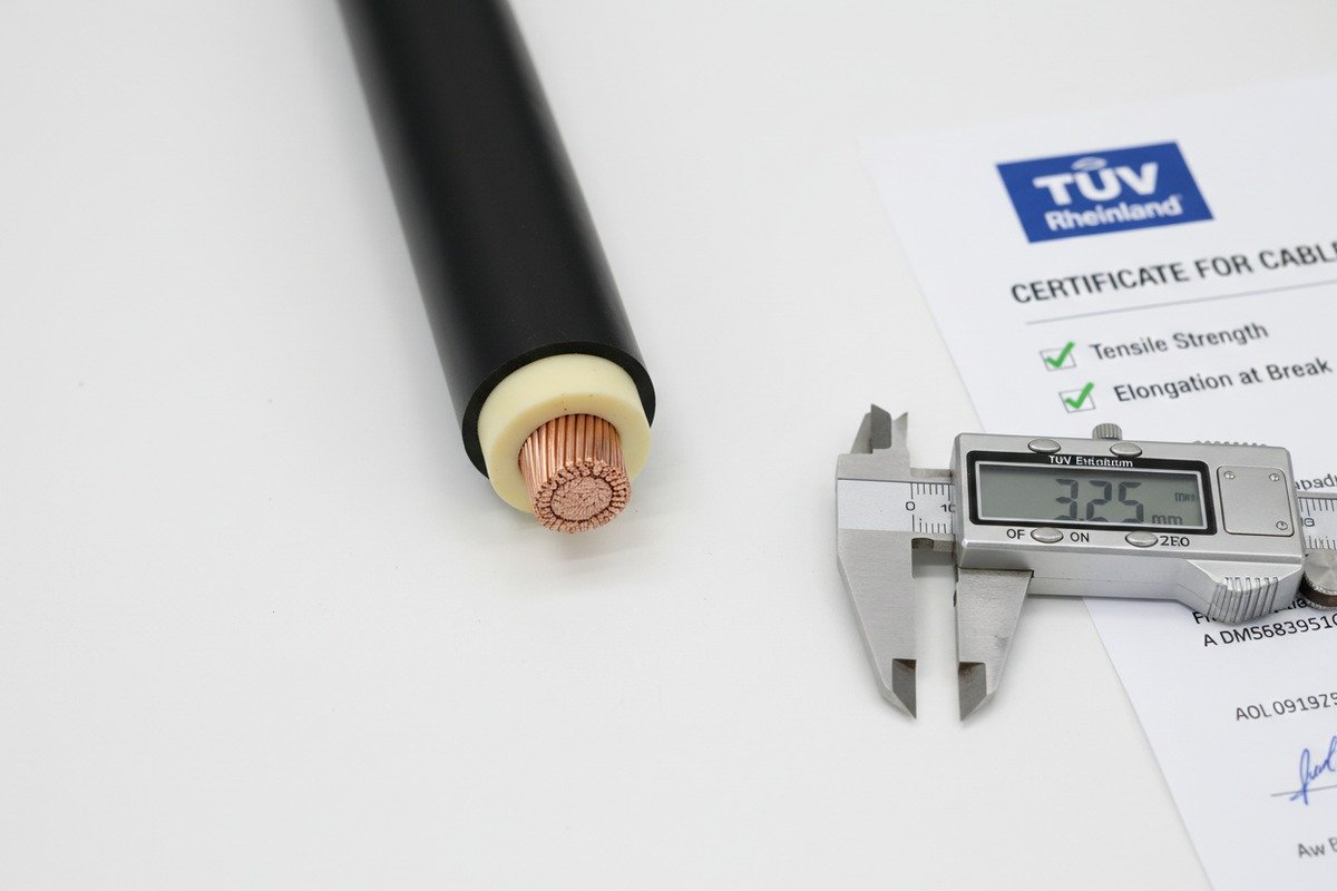
On our extrusion lines, we control two things very tightly: the cross-linking degree of the XLPO insulation and the purity of the copper conductor. These two factors directly determine how much pulling force a cable can absorb without permanent damage. We have seen competing products that look identical on the outside but fail at 60% of the rated tensile force because of shortcuts in material quality.
High-quality XLPO insulation with a cross-linking degree above 70% and oxygen-free copper conductors with tensile strength exceeding 200 N/mm² together create a cable that withstands significantly higher pulling forces without cracking, stretching, or conductor necking during installation.
Why Cross-Linking Degree Matters
XLPO stands for cross-linked polyolefin 9. The "cross-linked" part is not a marketing term—it describes a chemical process where polymer chains are bonded together into a three-dimensional network. This network gives the insulation its mechanical strength, heat resistance, and resistance to environmental stress cracking.
The cross-linking degree is measured as a percentage using the gel content method (per ASTM D2765 10 or equivalent). A higher percentage means more polymer chains are locked together. Below 65%, the insulation behaves closer to regular thermoplastic—it softens under heat and deforms under sustained pulling force. Above 70%, the material holds its shape and resists tearing even when stretched.
In our factory, we target a cross-linking degree of 72–80% for all H1Z2Z2-K and EN 50618 cables. We verify every production batch using gel extraction testing. This is not optional—it is the single most important quality gate for insulation mechanical performance.
Copper Conductor Quality
Not all copper is equal. Electrolytic tough pitch (ETP) copper with 99.9%+ purity has a conductivity of 100% IACS and a tensile strength of around 200–250 N/mm² in the annealed state. Cheaper recycled copper often has lower purity, which introduces brittleness and reduces both conductivity and tensile performance.
Conductor construction also matters. A finely stranded Class 5 flexible conductor distributes pulling force more evenly across all strands than a Class 2 solid or coarsely stranded conductor. This means fewer individual strand breaks during pulling, which preserves the cable's overall current-carrying capacity.
| Material Factor | Premium Quality | Budget Quality | Impact on Pulling Force |
|---|---|---|---|
| XLPO cross-linking degree | 72–80% | 50–65% | Premium handles 30–50% more tensile force before cracking |
| Copper purity | ≥ 99.9% ETP | 98–99% recycled | Higher purity = more ductile, less strand breakage |
| Conductor class | Class 5 (flexible) | Class 2 (rigid) | Flexible distributes force evenly, fewer individual strand failures |
| Insulation elongation at break | ≥ 150% | 80–120% | Higher elongation absorbs more pulling energy |
| Post-aging tensile retention | ≥ 75% | 50–65% | Premium maintains strength after years of UV and heat exposure |
The Hidden Cost of Cheap Materials
We once helped a distributor in Brazil troubleshoot a batch of cables from another supplier. The cables had passed a basic electrical test. But during a 40-meter conduit pull on a rooftop project, three out of ten cables showed visible insulation thinning—what engineers call "necking." The root cause was XLPO with a cross-linking degree of only 55%. The insulation stretched like taffy under pulling force instead of resisting it. The entire batch was rejected, and the project lost two weeks.
This is why we recommend that buyers request both the material data sheet and the gel content test report alongside the standard TÜV certificate. The cable may pass the minimum standard, but minimum is not always enough for demanding installation conditions.
What are the best ways to calculate maximum pulling tension to prevent internal cable damage during my project rollout?
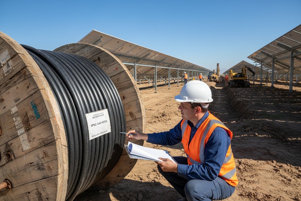
Our technical support engineers work with EPC teams on this calculation every week. The question comes up most often for utility-scale ground-mount projects in the Middle East and Africa, where cable runs can exceed 100 meters through underground ducts in extreme heat. Getting the pulling tension calculation wrong by even 20% can cause invisible conductor damage that shows up as resistance anomalies months later.
Calculate maximum pulling tension by multiplying the cable's weight per meter by the run length and the conduit friction coefficient, then verify the result stays below 25% of the cable's rated tensile break force—this safety margin prevents internal conductor stretching and insulation micro-cracking.
The Basic Pulling Tension Formula
The fundamental formula for a straight horizontal pull is:
T = L × W × f
Where T is the pulling tension in Newtons, L is the cable run length in meters, W is the cable weight in Newtons per meter, and f is the coefficient of friction between the cable jacket and the conduit inner surface.
For a typical 6 mm² H1Z2Z2-K cable weighing approximately 0.8 N/m, pulled through 50 meters of PVC conduit with a friction coefficient of 0.35, the calculation is:
T = 50 × 0.8 × 0.35 = 14 N
This seems low—and it is, for a straight run. But add bends, vertical rises, and multiple cables in the same conduit, and the number climbs fast.
Adjusting for Real-World Conditions
Every bend in the conduit path multiplies the tension by an exponential factor. A single 90° bend can increase pulling tension by 40–80%, depending on the bend radius and friction. Two 90° bends can more than double it. Vertical runs add the cable's own weight as a gravity component.
Here is a practical reference table for adjustment factors:
| Condition | Multiplier on Base Tension | Notes |
|---|---|---|
| Straight horizontal run | 1.0x | Baseline calculation |
| Single 90° bend (large radius) | 1.4–1.6x | Radius ≥ 10x cable diameter |
| Single 90° bend (tight radius) | 1.6–2.0x | Radius < 10x cable diameter |
| Two 90° bends | 2.0–3.2x | Compound effect |
| Vertical rise (per meter) | Add W per meter | Cable weight acts as direct tension |
| Multiple cables in conduit | 1.2–1.5x per additional cable | Jamming and friction increase |
| High temperature (>40°C) | 1.1–1.3x | Insulation softens, friction increases |
| With pulling lubricant | 0.5–0.7x | Reduces friction coefficient significantly |
The 25% Safety Rule
The industry standard safety margin is simple: never exceed 25% of the cable's rated tensile break force during installation. If your 6 mm² cable has a rated break force of 800 N, your maximum allowable pulling tension is 200 N.
Why 25% and not 50%? Because pulling forces are dynamic, not static. A crew pulling cable by hand or with a winch creates sudden jerks—peak forces that can be 2 to 3 times the average steady-state tension. The 25% rule accounts for these dynamic spikes.
Real-Time Monitoring on Site
For critical pulls—anything over 30 meters with bends, or any underground duct run—we recommend using a mechanical dynamometer or electronic tension meter inline with the pulling rope. This gives the crew a live reading of the actual force being applied. If the reading approaches the maximum allowable tension, they stop, apply lubricant, and reassess the route.
Some of our European EPC partners now use software-based pulling tension calculators that import cable weight data, conduit layout geometry, and friction coefficients to predict tension before the pull begins. This pre-calculation step has reduced our reported cable damage incidents by over 80% in the last three years.
What Happens When You Exceed the Limit
Exceeding the safe pulling tension causes three types of internal damage. First, individual copper strands break—reducing the effective conductor cross-section and increasing resistance. Second, the insulation thins at stress points (necking), creating weak spots vulnerable to voltage breakdown. Third, the bond between insulation and conductor can separate, allowing moisture ingress. None of these failures are visible from outside the cable. They only appear later as elevated temperature readings, reduced insulation resistance, or—worst case—arc faults.
Conclusion
Verifying solar PV cable mechanical strength is not optional—it is the foundation of a reliable, long-lasting solar installation. Request full tensile test reports, validate cross-linking quality, and always calculate your pulling tension with real-world safety margins before any cable leaves the drum.
Footnotes
1. Explains tensile strength as the maximum stress a material withstands before breaking under tension. ↩︎
2. Offers a comprehensive guide to universal testing machines and their functionality. ↩︎
3. Compares XLPO and XLPE insulation, highlighting their use in electrical insulation and cable applications. ↩︎
4. Provides information on IEC 62930 standard for PV cables, its scope, and importance. ↩︎
5. Details the EN 50618 standard for low smoke halogen-free, flexible, single-core power cables in PV systems. ↩︎
6. Covers UL 4703 standard for photovoltaic cables, their applications, and compliance. ↩︎
7. Explains NEC Article 690, covering installation and safety requirements for solar photovoltaic systems. ↩︎
8. Provides information on the IEC 62852 standard for connectors for DC applications in photovoltaic systems. ↩︎
9. Discusses radiation-crosslinked polyolefin, its properties, and advantages for demanding applications. ↩︎
10. Details ASTM D2765 standard test methods for determining gel content and swell ratio of crosslinked ethylene plastics. ↩︎