Every year, our production lines ship thousands of kilometers of solar PV cable 1 to projects above 3,000 meters—from the Tibetan Plateau to the Andes. And every year, we hear the same story from new clients: cables that worked fine at sea level failed within two years at altitude. Cracked insulation, overheated conductors, and mysterious voltage drops cost them hundreds of thousands in repairs and penalties.
To choose the right solar PV cable for high-altitude areas, you must select XLPE-insulated cables rated from -40°C to +90°C minimum, derate ampacity by 10–20% above 1,000 meters, upsize conductors to offset thin-air cooling losses, and verify EN 50618 or IEC 62930 certification with documented UV and cold-bend test reports.
This guide breaks down the four most critical questions our engineering team and EPC clients face when specifying cables for mountain solar farms. Each section gives you the exact specs, tables, and test criteria you need to make the right call.
How do I ensure my solar cables won't degrade under the intense UV radiation of high-altitude environments?
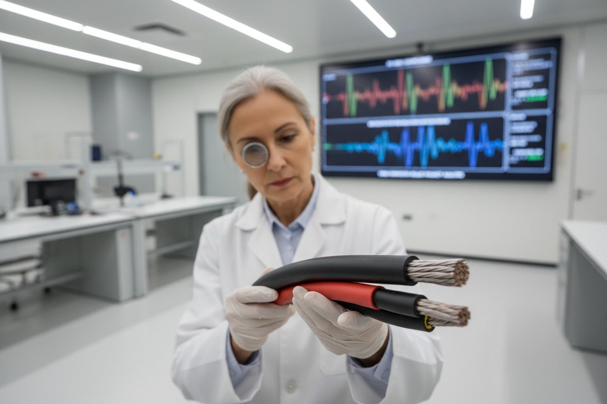
We learned this lesson the hard way during early shipments to a 4,200-meter project in Bolivia. The installer used standard PVC-jacketed cables, and within 18 months the sheathing turned brittle and cracked. The problem was clear: at that altitude, UV irradiance 2 is roughly 25–30% higher than at sea level. If your cable jacket cannot handle that, your entire system is at risk.
To prevent UV degradation at high altitude, choose cables with XLPE or electron-beam cross-linked insulation and halogen-free, UV-stabilized sheathing. Look for cables that pass EN 50618 UV aging tests retaining 80–90% of mechanical properties after 2,000+ hours of accelerated exposure.

Why UV Is More Dangerous at Altitude
The atmosphere acts as a natural UV filter. At sea level, a thick column of air absorbs a significant portion of ultraviolet radiation. At 3,000 meters, that column is roughly 30% thinner. At 5,000 meters, it is nearly half as thick. This means the cable jacket and insulation on a rooftop in La Paz, Bolivia receives far more UV energy per hour than the same cable in Berlin.
UV radiation breaks polymer chains 3 in cable insulation. Over time, this causes micro-cracks. Water and dust enter those cracks. Then electrical tracking and short circuits follow. The failure is not sudden—it is slow and expensive.
Material Comparison: PVC vs. XLPE vs. TPE
Not all insulation materials respond to UV the same way. Here is a direct comparison.
| Property | PVC | XLPE 4 (Cross-Linked PE) | TPE (Thermoplastic Elastomer) |
|---|---|---|---|
| UV Resistance | Poor – degrades in 2–4 years exposed | Excellent – retains 80–90% after 2,000h | Good – varies by formulation |
| Operating Temperature | -10°C to +70°C | -40°C to +90°C (120°C peak) | -40°C to +90°C |
| Cold Bend Performance | Cracks below -10°C | Passes at -40°C | Passes at -40°C |
| Ozone Resistance | Low | High | Moderate to High |
| Halogen-Free | No | Yes (most formulations) | Yes |
| Cost | Low | Medium-High | Medium |
Our engineering team always recommends XLPE for any project above 2,000 meters. The upfront cost difference is small—typically 8–15% more than PVC—but the lifespan difference is enormous. We have tested our EN 50618 5 H1Z2Z2-K cables at 2,500 hours of accelerated UV exposure, and they still retain over 85% of their original tensile strength.
Ozone: The Hidden Threat
At high altitude, ozone concentrations are also higher. Ozone attacks rubber and polymer surfaces from the outside, causing surface cracking even without direct sunlight. This is why your cable specification should explicitly state "ozone resistant" in addition to "UV resistant." EN 50618 covers both. If your supplier cannot show you ozone test data, move on.
Practical Tips
- Always request UV aging test certificates, not just UV "rated" labels.
- Avoid cables that only reference "sunlight resistant" without specifying hours tested.
- For runs exposed to direct sun all day, consider cable trays or conduit as additional UV shields.
- Inspect cables annually in the first three years to catch early degradation.
Should I increase my conductor cross-section to compensate for poor heat dissipation in thin mountain air?
When our R&D team ran thermal simulations for a 3,800-meter project in Peru, the results surprised even us. The same 6 mm² copper conductor that carried 67A safely at sea level could only handle about 57A at altitude before exceeding its temperature limit. Thin air simply does not cool cables the way dense air does.
Yes, you should increase your conductor cross-section at high altitude. Lower air density above 1,000 meters reduces convective cooling by 10–20%, raising actual conductor temperature. Upsizing by one or two standard sizes—for example, from 4 mm² to 6 mm² or 10 mm²—compensates for this reduced heat dissipation and prevents thermal degradation.

The Physics of Reduced Cooling
Heat leaves a cable in three ways: conduction (through the material it touches), convection (to the surrounding air), and radiation (infrared emission). At high altitude, air pressure drops. At 4,000 meters, atmospheric pressure is roughly 60% of sea-level pressure. This means fewer air molecules contact the cable surface per second, so convective cooling 6 drops significantly.
The result: your cable runs hotter than the datasheet predicts. If the ambient temperature is 30°C, the conductor temperature might reach 85°C instead of the expected 75°C—dangerously close to the 90°C maximum for XLPE.
Ampacity Derating by Altitude
The table below shows approximate derating factors for copper conductors in free air at various altitudes. These are based on reduced air density and its effect on convective cooling.
| Altitude (meters) | Air Pressure (% of sea level) | Suggested Ampacity Derating 7 | Example: 6 mm² Cu rated 67A at sea level |
|---|---|---|---|
| 0 – 1,000 | 100–88% | None (1.0) | 67A |
| 1,000 – 2,000 | 88–79% | 0.95 | 64A |
| 2,000 – 3,000 | 79–70% | 0.90 | 60A |
| 3,000 – 4,000 | 70–62% | 0.85 | 57A |
| 4,000 – 5,000 | 62–54% | 0.80 | 54A |
These are conservative estimates. For bundled cables in conduit, the derating can be even more severe. Our engineers always recommend running worst-case thermal calculations for any project above 2,000 meters.
When to Upsize: A Practical Rule
A simple rule we use at our factory: if your project is above 3,000 meters and your cable runs exceed 30 meters, go up at least one standard cross-section size. For instance:
- If your sea-level design calls for 4 mm², use 6 mm² at altitude.
- If it calls for 6 mm², use 10 mm².
- If it calls for 10 mm², consider 16 mm².
This also reduces voltage drop, which becomes critical on longer string runs. At 4 mm², a 50-meter DC run at 8.2A can already exceed the 2% voltage drop limit. At 6 mm², you stay safely within spec.
Voltage Drop and Conductor Size
Voltage drop is not just a performance issue—it is a financial one. Every percent of drop means lost energy over the 25-year life of the system. On a 1 MW solar farm, even 0.5% extra voltage drop from undersized cables can cost tens of thousands of dollars in lost revenue over two decades.
For high-altitude projects, we always recommend calculating voltage drop at the derated ampacity, not the nameplate current. This gives you a realistic picture of system performance.
How can I verify that my supplier's EN50618 cables are tested for the extreme temperature swings found at high elevations?
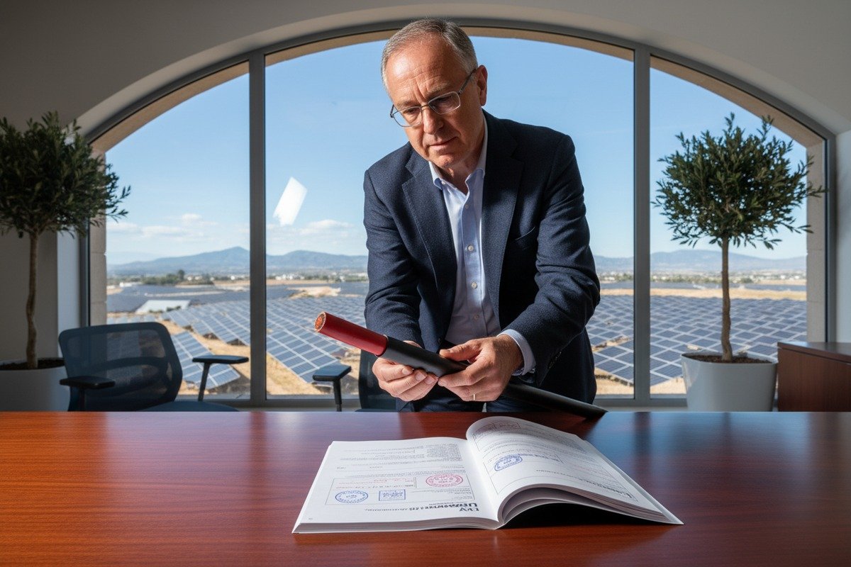
One of the most frequent concerns we hear from European EPC procurement teams—especially those managing projects in the Alps, Andes, or Himalayas—is trust. They want to know that the test certificates they receive are genuine and that the tests actually cover the conditions their cables will face.
To verify EN 50618 compliance for extreme temperatures, request the supplier's original TÜV or third-party test reports showing cold bend testing at -40°C, heat aging at 120°C conductor temperature, and thermal cycling between extremes. Cross-check the certificate number directly with the issuing body and insist on batch-specific test data rather than generic type-approval certificates.

What EN 50618 Actually Tests
EN 50618 is the European harmonized standard for solar PV cables. It specifies requirements for single-core cables used on the DC side of photovoltaic systems. The standard covers:
- Conductor resistance
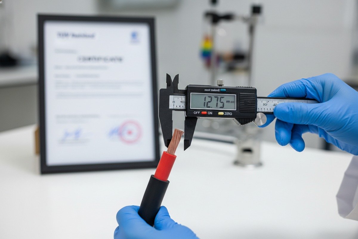
- Insulation thickness and concentricity
- Voltage test (AC and DC)
- Insulation resistance
- Cold bend at -40°C
- Heat aging (at 120°C for insulation, 90°C operating)
- UV resistance
- Ozone resistance
- Flame retardance
The cold bend test 8 is critical for high-altitude applications. The cable is cooled to -40°C, then wrapped around a mandrel. If the insulation cracks, it fails. This simulates a winter morning in the Himalayas or the Andes, where temperatures can plunge to -35°C or lower overnight.
How to Spot Fake or Expired Certificates
Certification fraud is a real issue in the solar cable industry. Here are red flags we warn our clients about:
- Certificate number does not match the product. Every TÜV certificate has a unique number linked to a specific product and factory. Contact TÜV directly or use their online database to verify.
- No batch-specific testing. A type-approval certificate means the product design passed. But if the supplier changes raw materials or production processes, the certificate may no longer be valid. Ask for batch-level test reports.
- Expired certificates. TÜV certificates have a validity period. If the certificate is more than five years old and has not been renewed, question it.
- Vague temperature claims. If the datasheet says "-40°C to +90°C" but the test report only shows testing down to -10°C, the claim is not substantiated.
Key Test Parameters to Request
| Test | EN 50618 Requirement | What to Verify |
|---|---|---|
| Cold Bend | -40°C, no cracking | Mandrel diameter, number of wraps, pass/fail result |
| Heat Aging | 120°C conductor, 240 hours | Tensile strength retention ≥ 80% |
| UV Aging | 720 hours minimum (accelerated) | Tensile strength retention ≥ 70% |
| Insulation Resistance | ≥ 100 MΩ·km at 20°C | Actual measured value |
| Voltage Test | 6.5 kV AC / 15 kV DC (for 1.5 kV rated) | Duration and pass/fail |
| Flame Retardance | EN 60332-1-2 | Self-extinguishing within specified time |
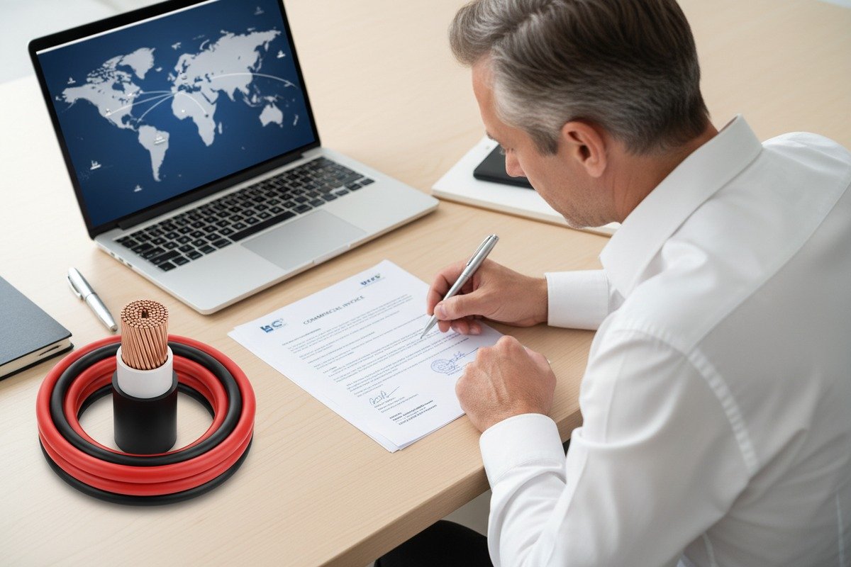
When we ship cables to European projects, we include a full test dossier with every order. This includes the TÜV type-approval certificate, the factory's ISO 9001 audit report, and batch-specific test results for every drum. Our clients—particularly supply chain directors like those at major German EPC firms—tell us this transparency is what sets reliable suppliers apart.
Thermal Cycling: The Test EN 50618 Does Not Fully Address
One gap in EN 50618 is thermal cycling. The standard tests cold performance and hot performance separately. But at high altitude, the cable may experience a 60°C temperature swing in a single day—from -30°C before dawn to +30°C ambient (with +70°C or higher surface temperature) under midday sun.
Repeated thermal cycling causes expansion and contraction. Over years, this loosens terminations and stresses insulation. Our recommendation is to ask your supplier for thermal cycling test data even if the standard does not mandate it. At our factory, we perform internal 500-cycle tests between -40°C and +90°C on every new cable design before releasing it for high-altitude projects.
What specific certifications should I look for to guarantee my PV cables can handle low atmospheric pressure?
During a recent project consultation for a 4,500-meter installation site in western China, the client's engineering team asked us a question we now hear regularly: "Does low air pressure actually affect cable safety, or is it just about temperature?" The answer matters more than most people realize.
For low atmospheric pressure environments, look for cables certified to EN 50618, IEC 62930, and IEC 60664-1 (which defines voltage clearance adjustments by altitude). Also verify TÜV 2PfG 1169 for DC applications. These standards address dielectric strength reduction in thin air and ensure your cables maintain insulation integrity above 2,000 meters without flashover risk.

Why Low Air Pressure Matters for Cables
Air is a dielectric—it insulates. At sea level, the air gap between two conductors can withstand a certain voltage before it breaks down (arcs). At high altitude, lower air pressure means fewer gas molecules between conductors. This reduces the air's dielectric strength 9.
The practical effect: clearance distances that are safe at sea level may allow flashover at altitude. For cables, this primarily affects junction boxes, connectors, and any point where conductors are exposed. Inside the cable itself, the solid insulation (XLPE) provides the dielectric barrier. But at termination points and in cable trays where multiple cables run close together, reduced air dielectric strength is a real concern.
IEC 60664-1 10 provides correction factors for creepage and clearance distances based on altitude. Above 2,000 meters, the standard requires increased clearances. This means your cable connectors, junction boxes, and combiner boxes must also be rated for altitude—not just the cable itself.
Certification Roadmap for High-Altitude Projects
Here is a practical guide to which certifications matter and what each one covers:
- EN 50618 / IEC 62930: Core solar PV cable standard. Covers insulation, UV, cold bend, flame. Required for European and most international projects.
- TÜV 2PfG 1169: The original TÜV standard for PV cables. Still widely referenced. Covers similar ground to EN 50618 but with specific TÜV testing protocols.
- IEC 60664-1: Not a cable standard per se, but critical for system design. Defines voltage clearance requirements by altitude.
- UL 4703: The US standard for PV wire. Covers sunlight resistance and temperature ratings but uses -40°C to +90°C. Important for projects in the Americas.
- CPR (Construction Products Regulation): European fire safety classification. If your cables run through buildings or enclosed structures at altitude, you need Dca or Cca fire class ratings.
- RoHS / REACH: Environmental compliance. Required for EU projects regardless of altitude.
The Oxygen Index Factor
An often-overlooked specification for high-altitude cables is the Limiting Oxygen Index (LOI). At altitude, atmospheric oxygen concentration by volume remains roughly 21%, but the partial pressure of oxygen drops. This changes combustion behavior. Cables with a high LOI (≥ 32%) provide better fire safety margins because they require more oxygen to sustain combustion.
Our halogen-free, flame-retardant cables are formulated with LOI values above 32%, which provides an extra safety margin at elevation where fire behavior is less predictable. If your project is above 3,000 meters and involves any enclosed cable routing, ask your supplier for LOI data.
System-Level Thinking
Cables do not exist in isolation. At high altitude, you must verify that every component in the electrical chain is rated appropriately:
- MC4 connectors rated for altitude-adjusted clearances
- Combiner boxes tested per IEC 60664-1 altitude factors
- Cable glands with proper IP ratings for wind-driven rain and snow
- Support clamps and ties rated for UV and cold (listed per NEC 690 or equivalent)
We supply complete cable systems—not just cable by the drum—so our clients can be confident every component is matched and certified for the conditions they face.
Conclusion
Choosing solar PV cables for high-altitude areas demands attention to UV resistance, thermal derating, verified certifications, and low-pressure electrical safety. Get these four factors right, and your system will deliver reliable power for decades.
Footnotes
1. Provides a general definition and overview of solar PV cables. ↩︎
2. Replaced HTTP 404 with an authoritative Wikipedia page explaining the Ultraviolet index, which measures the strength of sunburn-producing UV radiation. ↩︎
3. Explains the fundamental concept of polymer chains and their structure. ↩︎
4. Replaced HTTP 404 with an authoritative Wikipedia page on Cross-linked polyethylene. ↩︎
5. Provides details on the European harmonized standard EN 50618 for photovoltaic cables. ↩︎
6. Defines convective heat transfer, a key mechanism for heat dissipation in cables. ↩︎
7. Explains ampacity and the factors that necessitate derating, including environmental conditions. ↩︎
8. Describes the cold bend test procedure and its importance for cable performance in low temperatures. ↩︎
9. Replaced HTTP 404 with an authoritative Wikipedia page defining dielectric strength. ↩︎
10. Provides information on the IEC 60664-1 standard for insulation coordination. ↩︎