Every year, our production floor sees procurement teams who discovered cable failures only after installation — a costly nightmare that proper pre-shipment testing could have prevented entirely.
To test solar PV cable insulation and voltage resistance during procurement, use a megohmmeter for insulation resistance (IR) testing and a hipot tester for dielectric strength verification. Demand EN 50618 or IEC 62930 compliant test reports, require batch-specific certificates, and conduct on-site sample testing at the factory before shipment.
This guide walks you through every step of the testing process — from factory inspections to reading supplier reports — so you can catch substandard cables before they ever reach your project site Lockout/Tagout (LOTO) 1. Let's start with the standards that matter most.
How can I verify that my solar cables meet the EN 50618 insulation resistance standards during a factory inspection?
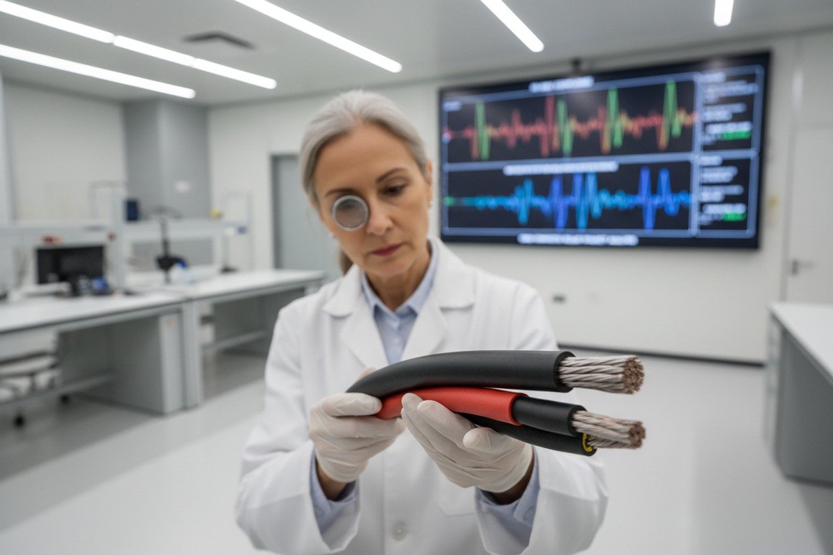
When we host factory inspections at our Hainan facility, the most common question from European EPC buyers is exactly this — how to verify IR standards on the spot.
To verify EN 50618 compliance during a factory inspection, use a calibrated megohmmeter set to 1000V DC and measure insulation resistance between the conductor and an outer electrode. EN 50618 requires a minimum of 1000 MΩ/km at 20°C. Always test multiple samples from different production batches.

Understanding the EN 50618 IR Requirement
EN 50618 2 is the European standard specifically designed for solar PV cables. It sets a very clear benchmark: insulation resistance 3 must exceed 1000 MΩ/km when measured at 20°C. This is significantly higher than the general IEC 62446 field minimum 4 of 1 MΩ. The reason is simple. PV cables live outdoors for 25+ years. They face UV, rain, heat, cold, and mechanical stress every single day. A cable that barely passes at 1 MΩ will likely fail within a few years.
Step-by-Step Factory IR Test
Here is the process our quality team follows, and the same process you should replicate or witness during your inspection:
- Select samples randomly. Pick at least 3 cable samples from different drums and different production batches. Do not let the supplier choose the samples for you.
- Prepare the megohmmeter. Use a device like the Fluke 1537 or a standard Megger rated for at least 1000V DC output. Confirm the calibration certificate is current.
- Set up the test. Strip back a short section of insulation at one end. Connect the red lead to the bare conductor. Wrap the outer insulation surface with bare copper wire or foil, then connect the black lead to this outer electrode.
- Apply voltage. Set the megohmmeter 5 to 1000V DC. Press and hold the test button for at least 60 seconds.
- Record the reading. The value must be normalized to MΩ/km based on sample length. Use the formula: IR (MΩ/km) = Measured IR (MΩ) × Length (km).
- Compare against the standard. The result must exceed 1000 MΩ/km at 20°C.
Factory Inspection IR Testing Checklist
| Inspection Step | What to Check | Pass Criteria |
|---|---|---|
| Sample selection | Random from ≥ 3 drums | Supplier cannot pre-select |
| Megohmmeter calibration | Valid calibration certificate | Within 12-month calibration cycle |
| Test voltage | 1000V DC applied | Stable voltage for 60 seconds |
| IR reading | Normalized to MΩ/km at 20°C | ≥ 1000 MΩ/km (EN 50618) |
| Temperature correction | Ambient temperature recorded | Correct reading if not at 20°C |
| Documentation | Photograph readings and setup | Signed by both parties |
Temperature Matters
IR values drop as temperature rises. If the factory floor is at 35°C, your readings will be lower than at 20°C. Most megohmmeters do not auto-correct for temperature. You need to apply a correction factor. A common rule of thumb: IR roughly halves for every 10°C increase above 20°C. So a reading of 600 MΩ/km at 30°C may actually correspond to about 1200 MΩ/km at 20°C. Always record the ambient temperature and ask the supplier for their temperature correction table.
What If the Cable Fails?
If any sample reads below 1000 MΩ/km after temperature correction, reject the batch. Do not accept explanations about humidity in the warehouse or "it will be fine after drying." A properly manufactured XLPO-insulated PV cable should pass this test consistently, regardless of minor ambient conditions. Our production line runs continuous IR monitoring, and any spool that dips below threshold gets flagged and quarantined automatically.
What specific voltage test reports should I demand from my supplier to ensure long-term system safety?
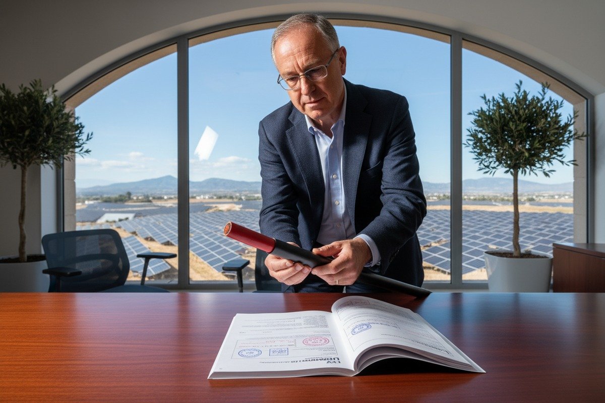
Our export team regularly works with German and Dutch EPC firms who maintain strict documentation checklists — and honestly, that rigor saves everyone headaches down the line.
Demand batch-specific voltage withstand (hipot) test reports showing the cable survived the rated test voltage (typically 2× rated voltage + 1 kV for 5 minutes) without breakdown. Also require insulation resistance reports, partial discharge test results, and valid TUV or third-party type test certificates referencing EN 50618 or IEC 62930.

The Three Reports You Must Have
Not all test reports are equal. Some suppliers hand you a generic type-test certificate from five years ago. That tells you nothing about the cable on the truck today. Here are the three categories of reports you should demand:
1. Type Test Report (One-time, standard-specific)
This proves the cable design meets the standard. It covers all tests in EN 50618 or IEC 62930 6, including voltage withstand, insulation resistance, mechanical, UV, and flame tests. It should come from a recognized lab like TUV, SGS, or Bureau Veritas.
2. Routine Test Report (Every production batch)
This is the critical one. It proves the specific batch you are buying was actually tested. It should include IR readings, voltage withstand results, and conductor resistance measurements. Insist on batch numbers that match your purchase order.
3. Partial Discharge (PD) Test Report (Recommended for 1500V systems)
PD testing detects tiny voids or defects inside the insulation that standard IR and hipot tests can miss. Partial Discharge (PD) Test Report 7 For high-voltage DC systems, especially 1500V strings, PD results give you an extra layer of confidence.
What the Voltage Withstand (Hipot) Report Should Show
| Report Element | Required Detail | Why It Matters |
|---|---|---|
| Test voltage applied | 2× U₀ + 1 kV (e.g., 2×1.0 kV + 1 kV = 3 kV for 1.0 kV rated cable) | Confirms the cable can handle voltage spikes |
| Test duration | 5 minutes (type test) or 1 minute (routine) | Short tests miss slow-developing breakdowns |
| Leakage current | Below manufacturer specification | High leakage means insulation weakness |
| Test temperature | Room temperature (20°C ± 5°C) | Ensures repeatable conditions |
| Result | Pass / No breakdown | Any breakdown = reject batch |
| Test equipment ID | Calibrated hipot tester 8 serial number | Ensures test equipment traceability |
Red Flags in Supplier Reports
Watch out for these warning signs:
- No batch number. A report without a batch number could apply to any production run — or none at all.
- Expired type test certificate. TUV certificates have a validity period, usually 5 years. If it expired, the supplier may have lost certification.
- Rounded numbers. If every IR reading is exactly 2000 MΩ/km across 10 samples, the data is likely fabricated. Real measurements show slight variations.
- Missing test equipment details. Legitimate labs always list equipment model and calibration status.
- No third-party involvement. If every report is "self-tested" with no independent lab verification, request a third-party audit.
How We Handle Documentation
On our end, every drum of cable that leaves the factory carries a QR code linking to its batch-specific test data. This includes IR values, hipot results, conductor resistance, and dimensional checks. We adopted this system because several of our European clients — particularly those supplying utility-scale solar farms — needed traceable documentation for grid-connection approvals. It is worth asking your supplier whether they offer similar traceability.
How do I conduct an on-site insulation test to prevent potential grid-connection failures in my project?
We have seen projects delayed by weeks because the grid authority rejected the installation due to low insulation resistance readings — a problem that a 10-minute test before laying cable would have caught.
Conduct an on-site insulation test by disconnecting all components, setting your megohmmeter to the appropriate DC voltage (500V or 1000V based on system rating), and measuring between each conductor and ground. For systems above 120V DC, IEC 62446 requires a minimum of 1 MΩ. Test each cable run individually before connecting modules or inverters.

Safety First: Preparation Protocol
Before you touch any cable with a test instrument, follow these steps strictly:
- Lockout/Tagout (LOTO). Isolate all power sources. Turn off inverters, disconnect DC disconnectors, and open string combiner boxes.
- Verify zero voltage. Use a multimeter to confirm that both positive-to-ground and negative-to-ground read 0V. If modules are connected, they will generate voltage even in low light. Disconnect them.
- Discharge capacitance. Some cables and system components hold residual charge. Wait at least 30 seconds after disconnecting, or use a discharge resistor.
- Wear PPE. Insulated gloves rated for your system voltage. Safety glasses. Non-conductive footwear.
On-Site Test Procedure
Here is a straightforward procedure that works for both rooftop and utility-scale sites:
Step 1: Identify the cable run you want to test. Each positive and negative homerun cable should be tested separately.
Step 2: Connect the megohmmeter's red lead to the cable conductor at the combiner box end. Connect the black lead to the grounding bar or equipment ground.
Step 3: Select the test voltage. Use the table below to choose the right setting:
| System Voltage (V DC) | Recommended Test Voltage | Minimum IR (IEC 62446) |
|---|---|---|
| < 120V | 250V DC | Not required by IEC |
| 120V – 500V | 500V DC | ≥ 1 MΩ |
| 500V – 1000V | 1000V DC | ≥ 1 MΩ |
| 1000V – 1500V | 1000V DC | ≥ 1 MΩ |
Step 4: Press and hold the test button for 60 seconds. Record the stabilized reading.
Step 5: Repeat for the other conductor (if you tested positive first, now test negative).
Step 6: Optionally, test positive-to-negative (P-N) to check for inter-conductor insulation integrity.
Interpreting Your Results
The IEC 62446 minimum is 1 MΩ. But in practice, a healthy new cable should read well above 100 MΩ. If you get a reading between 1 MΩ and 20 MΩ on a brand-new cable, something is wrong. Common causes include:
- Moisture ingress at a poorly sealed connector or junction box.
- Damaged insulation from rough handling during installation — dragged across sharp metal edges, kinked around tight corners, or crushed under heavy equipment.
- Contaminated cable ends — dust, dirt, or salt spray on exposed insulation surfaces can create surface conduction paths.
What to Do When Readings Are Low
Do not immediately blame the cable. First, clean the exposed ends with isopropyl alcohol and a lint-free cloth. Let them dry completely. Retest. If the reading improves to normal levels, the issue was surface contamination. If it stays low, isolate shorter sections of the run to pinpoint the fault location. Replace the affected section before grid connection.
Field vs. Factory Standards
There is an important distinction here. The factory test per EN 50618 demands ≥ 1000 MΩ/km. The field test per IEC 62446 demands only ≥ 1 MΩ for the entire circuit. The field standard is much lower because it accounts for real-world factors: connectors, junction boxes, cable lengths, and environmental conditions. However, if your field reading on a single new cable is anywhere near 1 MΩ, treat it as a serious warning sign.
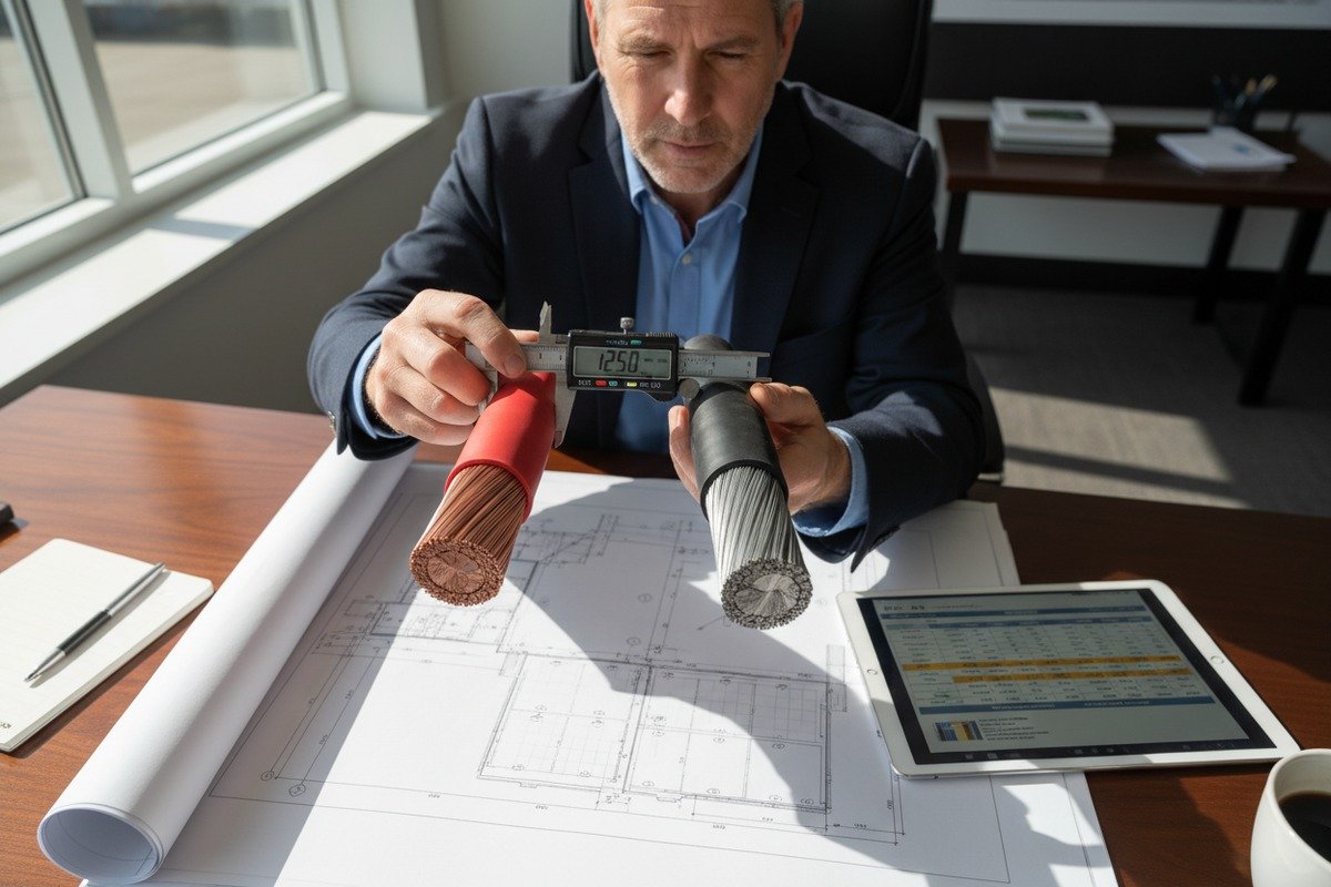
Can I identify if my supplier is using substandard XLPO insulation through a simple voltage resistance check?
During a recent pre-shipment inspection for a large Middle Eastern solar farm, our quality engineers caught an interesting case — a competitor's cable samples showed suspiciously low IR readings at elevated temperatures, hinting at inferior insulation compound.
Yes, a voltage resistance check can reveal substandard XLPO insulation, but it works best when combined with elevated-temperature testing. Genuine cross-linked polyolefin (XLPO) maintains high insulation resistance above 90°C, while low-grade or non-cross-linked material shows a sharp IR drop. A standard hipot test at room temperature may not catch all defects.

Why XLPO Quality Varies
XLPO — cross-linked polyolefin 9 — is the insulation material specified in EN 50618 and most modern PV cable standards. Cross-linking is a chemical process that creates molecular bonds between polymer chains. This gives the material its heat resistance, mechanical toughness, and long-term UV stability. The problem is that cross-linking requires precise control of temperature, pressure, and curing agents. Cut corners on any of these, and you get a material that looks identical on the outside but degrades much faster.
Some low-cost manufacturers reduce the cross-linking degree to save time and money. Others substitute cheaper base polymers. The cable passes a room-temperature IR test just fine. But expose it to 90°C or above — temperatures easily reached on a rooftop in summer — and the IR drops dramatically.
The Hot IR Test Method
This is the most practical field-level check for XLPO quality:
- Take a 1-meter cable sample.
- Place it in an oven or heat chamber set to 90°C for 4 hours.
- While still hot, perform an IR test using a megohmmeter at 500V DC.
- Compare the reading to the room-temperature result.
Properly cross-linked XLPO should retain at least 50% of its room-temperature IR value at 90°C. If the IR drops below 100 MΩ/km at 90°C, the cross-linking is likely insufficient.
Room Temperature Hipot: What It Can and Cannot Tell You
A standard voltage withstand test at room temperature applies high voltage (e.g., 3.5 kV for 5 minutes) and checks for breakdown. This catches gross manufacturing defects:
- Air bubbles or voids in the insulation
- Contamination particles embedded during extrusion
- Insulation that is too thin at certain points
However, it does not catch:
- Low cross-linking degree
- Gradual UV degradation potential
- Long-term thermal aging characteristics
Think of the hipot test as a pass/fail gate. It tells you the cable is not immediately dangerous. But it does not predict 25-year performance.
Combining Tests for Confidence
For maximum confidence, use this approach during procurement:
| Test | What It Detects | Limitation |
|---|---|---|
| Room-temp IR (1000V DC) | Moisture, contamination, gross defects | Misses cross-linking issues |
| Hot IR (90°C, 500V DC) | Insufficient cross-linking, poor XLPO quality | Requires oven, not always available on-site |
| Hipot (3.5 kV, 5 min) | Voids, thin spots, breakdown risk | Does not predict aging performance |
| Partial discharge (PD) | Micro-voids, localized weak spots | Requires specialized equipment |
| Third-party lab aging test | Long-term thermal/UV stability | Takes weeks, not suitable for urgent orders |
Visual and Tactile Clues
Beyond electrical testing, experienced inspectors look for physical signs of substandard XLPO:
- Surface texture. High-quality XLPO has a smooth, slightly matte finish. Cheap material often feels waxy or overly glossy.
- Flexibility. Properly cross-linked XLPO is flexible but returns to shape. Poor material may feel stiff or crack when bent sharply at low temperatures.
- Cut cross-section. When you slice the insulation with a sharp blade, good XLPO shows a clean, uniform cross-section. Bad material may show layering, discoloration, or uneven density.
Our Approach to XLPO Quality Control
On our production lines, we run continuous cross-linking degree tests using the hot-set method per EN 60811-507. A sample is placed under mechanical load at 200°C. If the elongation exceeds 175% or does not recover after cooling, the batch is rejected. We make these test results available to our buyers because transparency builds trust — and because we know that a rejected cable on-site costs everyone far more than a rejected batch in the factory.
Conclusion
Testing insulation and voltage resistance during procurement is not optional — it is the most cost-effective quality gate between a reliable 25-year solar installation and an expensive failure.
Footnotes
1. Describes the essential safety procedure for controlling hazardous energy during maintenance. ↩︎
2. Provides details on the European standard for photovoltaic cables. ↩︎
3. Explains the concept of insulation resistance and its importance in electrical systems. ↩︎
4. Explains the field-level insulation resistance requirements for PV systems. ↩︎
5. Defines the instrument used for measuring electrical resistance in insulators. ↩︎
6. Outlines the international standard for photovoltaic cable requirements and testing. ↩︎
7. Details a specialized test for detecting insulation defects in high-voltage cables. ↩︎
8. Describes the high-potential test equipment for verifying dielectric withstand strength. ↩︎
9. Provides an academic overview of cross-linked polyolefins and their properties. ↩︎
10. Explains the characteristics and applications of cross-linked polyolefin insulation. ↩︎