Every year, our technical support team receives hundreds of inquiries from installers and EPC firms who discovered—too late—that their solar cables didn't match their connectors or module wiring layout.
To choose connector-compatible solar PV cables, match the cable's cross-section, voltage rating, and outer diameter to your connector type (typically MC4), then verify compatibility with your series or parallel module wiring configuration. Always confirm certifications like TUV, UL, and IP67/IP68 ratings for long-term field reliability.
This guide breaks down every technical factor you need to consider confirm certifications 1. We'll walk through MC4 compatibility 2, cross-section selection for different wiring layouts, insulation longevity, and high-voltage string requirements. Let's start with the most common question we hear on our production floor.
How do I ensure my H1Z2Z2-K solar cables are perfectly compatible with standard MC4 connectors?
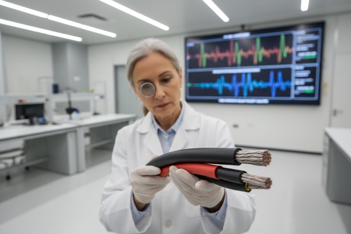
When our engineers test new cable batches against MC4 connector assemblies 3, even a 0.2mm deviation in outer diameter can turn a secure connection into a liability.
H1Z2Z2-K solar cables achieve perfect MC4 compatibility when their outer diameter falls within 5.0–6.4mm, the conductor is tinned copper with a 4mm² or 6mm² cross-section, and crimping uses manufacturer-specified die sets. Always verify TUV 2PfG 1169 and IEC 62930 certifications on both cable and connector.

Getting this right is not just about plugging things together Voltage Drop Calculation 4. It involves understanding the physical anatomy of both the cable and the connector, and making sure every dimension, material, and rating aligns.
Understanding MC4 Connector Anatomy
MC4 connectors use a pin-and-socket design. The male connector houses a 4mm pin. The female connector has a matching socket. Both snap together with a locking clip rated to IP67 or IP68 damp heat testing 5. The cable enters through a compression gland at the back. This gland seals around the cable's outer jacket. If the jacket diameter is too thin, the gland won't seal. Too thick, and you can't insert the cable at all.
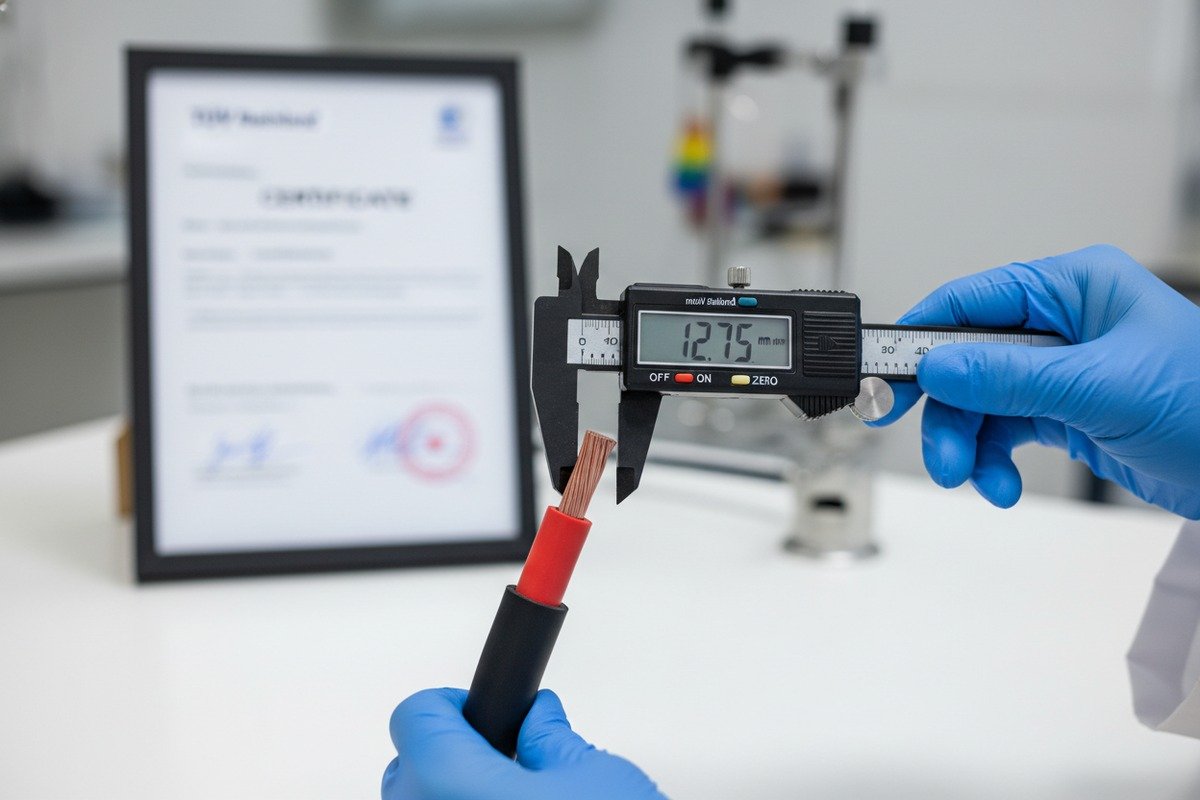
Critical Dimensions to Match
Here is a quick reference table for matching H1Z2Z2-K cables to MC4 connectors:
| Parameter | MC4 Connector Requirement | H1Z2Z2-K 4mm² Cable | H1Z2Z2-K 6mm² Cable |
|---|---|---|---|
| Conductor diameter | Fits 4mm pin crimp | 2.0–2.2mm | 2.6–2.8mm |
| Cable outer diameter | 5.0–6.4mm (typical gland range) | 5.0–5.8mm | 5.6–6.4mm |
| Voltage rating | 1000V DC or 1500V DC | 1000/1500V DC | 1000/1500V DC |
| Current rating | 20–30A continuous | ~40A (cable capacity) | ~55A (cable capacity) |
| Crimp type | Requires MC4-specific die | Tinned copper strand | Tinned copper strand |
Polarity: Don't Assume, Always Test
Most sources state that the female MC4 connector carries the positive lead and the male carries the negative. This holds true for about 90% of modules on the market. But it is not universal. Some manufacturers reverse the convention. Before you connect a single cable, use a multimeter under sunlight to confirm polarity at the module leads. Mistakes here cause reverse current flow and can damage inverters or bypass diodes.
Crimping Quality Matters More Than You Think
On our production line, we've seen the difference between a proper crimp and a poor one under thermal cycling tests. A well-crimped MC4 joint maintains contact resistance below 0.5mΩ. A bad crimp can exceed 5mΩ, creating a hot spot that degrades over time. Always use the crimping tool specified by the connector manufacturer—generic pliers are not acceptable. The crimp must pass a pull-test of at least 50N.
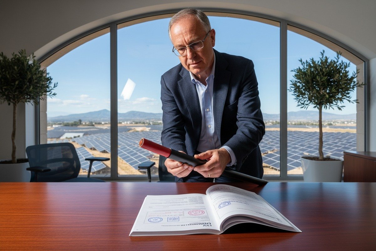
Certification Cross-Check
Your H1Z2Z2-K cable should carry TUV 2PfG 1169 6 or EN 50618 certification. Your MC4 connectors should carry TUV and UL 6703 listings. Mixing a certified cable with an uncertified generic connector voids the system's compliance. In Europe, inspectors will flag this. In Germany especially, Klaus and his team at the EPC level reject entire shipments over mismatched certifications. We print our TUV certificate numbers directly on the cable jacket so verification is immediate on-site.
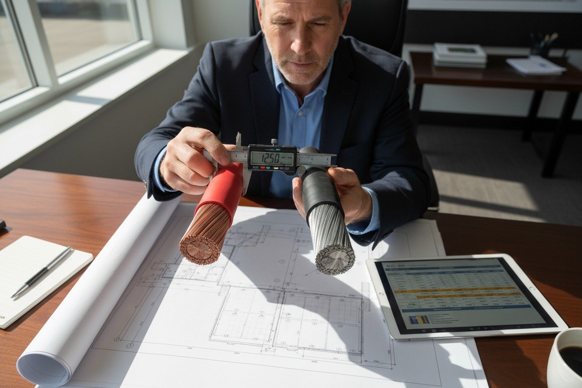
Which cable cross-section should I select for my specific series or parallel module wiring layout?
Choosing the wrong cable cross-section is one of those silent errors—our export team has seen projects lose 3–5% of annual yield simply because the wire gauge couldn't handle the current over the run length.
For series strings, 4mm² H1Z2Z2-K cable handles most residential runs under 30 meters at up to 10–12A. For parallel combiner outputs carrying 30A or more, upgrade to 6mm² or 10mm². Always calculate voltage drop: keep it below 2% of the string voltage for optimal energy harvest.

The wiring layout of your PV array directly determines how much current flows through each cable segment. Series connections increase voltage but keep current equal to a single module's output. Parallel connections keep voltage the same but multiply the current. This distinction drives your cable sizing decision.
Series Wiring: Voltage Stacks, Current Stays Low
In a series string, you connect the positive lead of one module to the negative lead of the next. If each module has an open-circuit voltage (Voc) of 40V and you wire 10 modules in series, the string voltage reaches 400V. The current stays at a single module's short-circuit current (Isc)—typically 10–12A for residential modules.
For most residential series strings, a 4mm² cable is sufficient. The module leads are usually pre-attached at 4mm², and the MC4 connections are plug-and-play between modules. You only need extension cables when running from the string end to the inverter.
Parallel Wiring: Current Multiplies
When you parallel two strings, the current doubles. Four strings in parallel means four times the single-module Isc. This is where under-sizing cables becomes dangerous. A 4mm² cable rated for 40A at the cable level may seem fine for 40A combined current, but the voltage drop over a long run can push losses beyond acceptable limits.
Voltage Drop Calculation
Use this simplified formula:
Voltage Drop (V) = 2 × Length (m) × Current (A) × Resistivity (Ω·mm²/m) ÷ Cross-Section (mm²)
For copper at 20°C, resistivity is approximately 0.0175 Ω·mm²/m.
| Scenario | Cross-Section | Current | Cable Length (one way) | Voltage Drop | % Drop (at 400V string) |
|---|---|---|---|---|---|
| Single string to inverter | 4mm² | 10A | 20m | 1.75V | 0.44% |
| Single string to inverter | 4mm² | 10A | 50m | 4.38V | 1.09% |
| 4 strings paralleled to combiner | 6mm² | 40A | 15m | 3.50V | 0.88% |
| 4 strings paralleled to combiner | 6mm² | 40A | 40m | 9.33V | 2.33% |
| 4 strings paralleled to combiner | 10mm² | 40A | 40m | 5.60V | 1.40% |
Notice the last row. Upgrading from 6mm² to 10mm² on a 40m parallel run brings the voltage drop from 2.33% back under the 2% threshold. This is exactly the kind of decision that separates a well-designed system from one that underperforms for 25 years.
Branch Connectors for Parallel Configurations
When paralleling strings, Y-branch or T-branch MC4 connectors combine two positive leads into one. These must be rated for the combined current. A standard MC4 Y-branch handles 30A per leg and 30A on the combined output. For four strings, you'll need to cascade two Y-branches or use a dedicated combiner box. Our 6mm² cables are specifically designed with an outer diameter that fits both standard MC4 connectors and the larger-bore Y-branch glands.
How can I verify that the cable insulation will maintain a secure, leak-proof connection over a 25-year lifespan?
One of the toughest questions our R&D department faces during accelerated aging tests is not whether the cable will survive year one, but whether the insulation-connector interface will still be watertight in year twenty.
Verify 25-year insulation integrity by confirming the cable uses electron-beam cross-linked polyolefin (XLPO) insulation rated to 120°C, carries TUV 2PfG 1169 or EN 50618 certification, passes 1000 hours of damp heat testing (85°C/85% RH), and maintains IP67/IP68 sealing when mated with the specified connector under thermal cycling.

A cable might look fine on day one. But UV radiation, thermal cycling between -40°C and +90°C, and constant moisture exposure will attack the insulation and the connector seal relentlessly. Here's how to verify your cable can handle it.
The Role of XLPO Insulation
Cross-linked polyolefin (XLPO) is the industry-standard insulation material for H1Z2Z2-K solar cables. electron-beam cross-linked polyolefin (XLPO) insulation 7 The electron-beam cross-linking process creates molecular bonds that resist thermal degradation far better than standard PVC or non-cross-linked polyethylene. On our production lines, we control the cross-linking degree to between 65–75%, which balances flexibility with long-term thermal stability.
Key Aging Tests You Should Ask About
When evaluating a cable supplier, request documentation for these specific tests:
| Test | Standard | Conditions | Pass Criteria |
|---|---|---|---|
| Damp heat | IEC 62930 / EN 50618 | 85°C, 85% RH, 1000 hours | No cracking, insulation resistance >100MΩ |
| UV resistance | EN 50618 Annex | 720 hours UV-B exposure | No surface cracking, <10% elongation loss |
| Thermal cycling | IEC 62930 | -40°C to +90°C, 200 cycles | No jacket shrinkage >2%, no conductor exposure |
| Ozone resistance | EN 50396 | 200 pphm O₃, 48 hours | No surface cracking visible at 2× magnification |
| Acid/alkali resistance | EN 60811-404 | Immersion in H₂SO₄ and NaOH | No swelling >10%, no mechanical property loss |
The Connector-Cable Interface Is the Weak Point
The cable itself might last 30 years. But the junction where the cable enters the MC4 connector is the most vulnerable point. This is where moisture ingress happens. The compression gland must maintain a seal even as the cable jacket expands and contracts through thousands of thermal cycles.
We test our cables mated with certified MC4 connectors under simulated 25-year conditions. The outer jacket must not shrink more than 2% in length after thermal cycling—otherwise the gland loses compression and the IP67 seal breaks down. If your supplier cannot show thermal cycling data with the cable and connector mated together, that's a red flag.
Field Inspection Tips
After installation, visually inspect every connector junction annually for the first three years. Look for:
- White residue around the gland (salt or mineral deposits indicating moisture entry)
- Discoloration or bulging of the cable jacket near the connector
- Any visible gap between the gland nut and the cable surface
If you spot any of these, disconnect with a proper MC4 unlocking tool and re-terminate. Do not simply push the connector back together—this compresses degraded sealing surfaces and makes the problem worse.
The CPR Fire Safety Dimension
For European installations, the cable's Construction Products Regulation (CPR) 8 fire class matters. A cable rated Dca-s2,d2,a1 ensures limited flame spread, low smoke, and no acid gas emission. This is not just a building code issue—fire-resistant insulation also tends to age better because the flame-retardant additives improve overall polymer stability. Our H1Z2Z2-K cables meet Cca and Dca ratings verified through independent EN 50575 testing.
What technical specifications should I look for to prevent connection failures in high-voltage PV module strings?
Our testing lab has simulated arc-fault scenarios at 1500V DC, and the difference between a cable rated for 1000V and one properly certified for 1500V is the difference between a safe disconnect and a fire.
For high-voltage strings (1000–1500V DC), select cables with a system voltage rating matching or exceeding the string's maximum open-circuit voltage at the coldest site temperature, verify the connector's DC breaking capacity, ensure the cable passes partial discharge testing below 1pC, and confirm the complete assembly meets IEC 62852 or UL 6703 for connectors plus EN 50618 or UL 4703 for cables.

High-voltage strings are the backbone of modern utility-scale and large commercial PV plants. They reduce the number of strings and combiner boxes needed, which lowers installation costs. But they also raise the stakes for every connection point. A failure at 1500V DC is far more dangerous than at 600V.
Why Cold Temperature Matters for Voltage Rating
Module open-circuit voltage (Voc) increases as temperature drops. A module rated at 40V Voc at standard test conditions (25°C) might reach 44V Voc at -10°C. If your string has 34 modules in series, the cold-temperature Voc could reach 1496V—dangerously close to the 1500V system limit. Your cable and connectors must be rated for the system voltage, not just the nominal operating voltage.
Calculate the maximum string voltage using the module's temperature coefficient for Voc (typically -0.27% to -0.35% per °C) and the minimum expected ambient temperature at the site.
Partial Discharge: The Hidden Killer
At voltages above 1000V DC, partial discharge (PD) becomes a real threat. PD is a localized electrical breakdown within the insulation that doesn't fully bridge the insulation gap—yet. Over months or years, it erodes the insulation from inside. Cables designed for 1500V systems must pass partial discharge testing 9 with PD levels below 1 picocoulomb (pC) at 1.5× rated voltage.
Not all manufacturers test for this. When we produce 1500V-rated H1Z2Z2-K cable, every production batch undergoes PD testing per IEC 62930. If your supplier can't provide PD test reports, their 1500V rating may be based only on withstand voltage, which is not the same thing.
DC Breaking Capacity of Connectors
This is often overlooked. An MC4 connector rated for 1500V DC must also have a certified DC breaking capacity. DC arcs don't self-extinguish like AC arcs. When you disconnect a loaded DC connector, the arc can sustain itself and cause a fire. Standard MC4 connectors are "make under load" but NOT "break under load." You must de-energize the string (cover the modules or open the inverter's DC disconnect) before unplugging MC4 connectors.
Some newer MC4-compatible connectors from brands like Stäubli offer limited DC break capacity, but this must be explicitly stated in the datasheet. Never assume a connector can be disconnected under load.
Creepage and Clearance Distances
At 1500V DC, the physical distances between live parts and grounded surfaces inside the connector become critical. Creepage and Clearance Distances 10 IEC 62852 specifies minimum creepage (surface distance) and clearance (air distance) requirements. Cheap generic connectors often fail here—their internal geometry simply wasn't designed for 1500V operation, even if the plastic housing looks identical to a certified unit.
System-Level Checklist for High-Voltage Strings
Before finalizing your cable and connector order for a high-voltage system, verify every item below:
- Cable voltage rating ≥ maximum cold-temperature string Voc
- Connector voltage rating matches cable voltage rating
- Partial discharge test report: <1pC at 1.5× rated voltage
- Connector IP rating: IP67 minimum, IP68 for ground-mount
- Cable temperature rating: -40°C to +90°C ambient
- Connector DC breaking capacity: understand limits (typically zero for standard MC4)
- Both cable and connector carry matching certification (TUV, UL, or both)
- Crimp contact resistance verified: <0.5mΩ per joint
- Cable pull-out force from connector: >50N after thermal cycling
We supply complete cable-connector assemblies pre-terminated in our factory for high-voltage projects. This eliminates field crimping variability and ensures every joint meets our internal quality standard—which exceeds TUV requirements by a margin we've built into our process over 30 years.
Footnotes
1. Highlights the necessity of verifying certifications for long-term field reliability of solar components. ↩︎
2. Explains MC4 connector standards, features, and the importance of compatibility in solar installations. ↩︎
3. Explains the importance of precise cable dimensions for secure MC4 connector assemblies. ↩︎
4. Explains the concept of voltage drop in PV systems and provides a formula for calculation. ↩︎
5. Explains damp heat testing as a critical method for verifying 25-year insulation integrity of solar cables. ↩︎
6. Explains the withdrawal of TUV 2PfG 1169 and the current applicable standards for PV cables. ↩︎
7. Explains XLPO insulation properties, including thermal resistance, UV resistance, and chemical resistance. ↩︎
8. Explains the European Construction Products Regulation and its fire classification system for cables. ↩︎
9. Explains partial discharge testing as a method to detect insulation defects in high-voltage cables. ↩︎
10. Defines creepage and clearance distances and their importance in high-voltage electrical design and safety. ↩︎