Every year, our quality team investigates returned cable samples from solar farms where connectors have loosened, insulation has cracked, or resistance has crept upward coefficient of thermal expansion (CTE) 1. The root cause is almost always the same: thermal expansion stress 2 from daily temperature cycling that was never properly evaluated before installation. If you are sourcing solar PV cables for a 25-year project, ignoring this issue can cost you the entire system.
To evaluate solar PV cable thermal expansion during temperature cycling, you need to measure the coefficient of thermal expansion (CTE) mismatch between the conductor and insulation, run standardized thermal cycling tests from -40°C to +90°C for at least 200 cycles, and inspect for cracking, resistance rise, and insulation breakdown afterward.
This guide walks you through the precise measurements, test standards, design strategies, and supplier verification steps you need. Let's start with the hands-on measurement process.
How do I accurately measure the thermal expansion of H1Z2Z2-K cables during extreme temperature cycling?
When we run thermal cycling trials on our H1Z2Z2-K production batches, the gap between lab results and real-world performance always comes down to how carefully you control the test variables. Many buyers underestimate this.
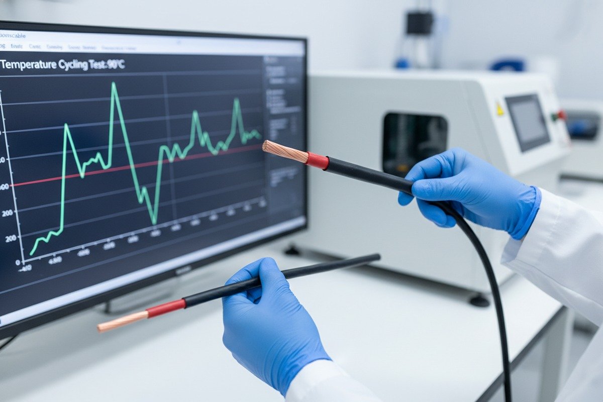
To accurately measure thermal expansion of H1Z2Z2-K cables, cycle samples between -40°C and +90°C at ramp rates below 100°C per hour, with dwell times of at least 10 minutes at each extreme. After 200 cycles minimum, measure dimensional changes, resistance, and insulation integrity.

Understanding CTE Mismatch
The core problem is simple. Copper expands at about 17 ppm/°C. XLPO insulation 3 expands at roughly 150–200 ppm/°C. That is a 10x difference. Every time your cable heats up under the sun and cools down at night, the insulation moves far more than the conductor inside it. This creates shear stress at the interface. Over thousands of cycles, this stress leads to delamination, microcracks, and loose connections.
For aluminum conductors, the mismatch is slightly less severe because aluminum has a CTE of about 23 ppm/°C. But the insulation still moves roughly 7–8 times more.
Setting Up Your Test
Here is a practical test protocol based on IEC 61215 principles 4 adapted for cables:
- Cut at least five cable samples to 1-meter lengths.
- Place them in a climate chamber with calibrated thermocouples attached at three points along each sample.
- Program the chamber for -40°C to +90°C cycling.
- Set the ramp rate to no more than 100°C per hour. Faster ramps create unrealistic thermal shock.
- Hold at each extreme for a minimum of 10 minutes. Some protocols use 30-minute dwells for better data.
- Run at least 200 cycles. For desert or high-altitude sites, consider 400–600 cycles.
What to Measure After Cycling
| Parameter | Method | Pass Criteria |
|---|---|---|
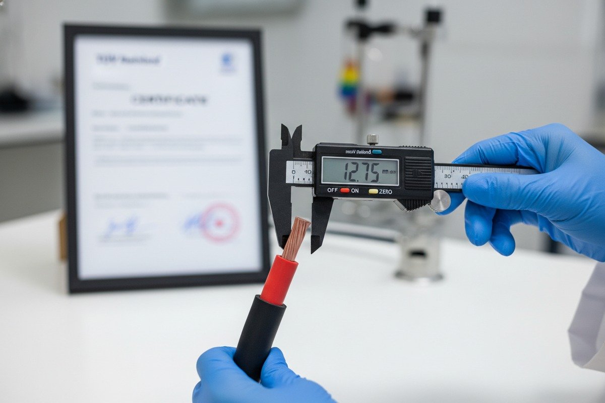
| Dimensional change (length) | Precision caliper at 23°C | Less than 0.5% permanent elongation |
| Conductor resistance | 4-wire Kelvin measurement 5 | Less than 10% increase from baseline |
| Insulation resistance | Megohmmeter at 500V DC | Greater than 100 MΩ·km |
| Visual inspection | 10x magnification | No cracks, no delamination |
| Cold bend test | Bend around mandrel at -40°C | No cracking or fracture |
| Tensile strength retention | Pull test per IEC 60811 | Greater than 80% of pre-test value |
Rapid vs. Standard Cycling
There is a growing debate in the industry about accelerated testing. Some labs use ramp rates of 6.5°C per minute with 16-minute dwells to compress testing timelines from months to weeks. Our engineering team has found that rapid cycling is useful for screening, but it can overemphasize certain failure modes while missing creep-related degradation. For critical procurement decisions, we always recommend the full standard-rate protocol alongside any accelerated test.
The Cold Side Matters Most
Many people focus on the hot extreme. But in our experience shipping cables to projects in Northern Europe and high-altitude Latin American sites, the cold side is where most failures happen. At -40°C, XLPO insulation stiffens dramatically. If the cable was bent or stressed during installation, this stiffening creates crack initiation points. After 200 thermal cycles, those tiny cracks propagate until insulation integrity fails completely.
What specific TUV or EN 50618 test data should I request to verify the thermal stability of my solar cables?
Our sales team regularly fields requests from European EPC firms who ask for "TUV certificates." But a certificate alone tells you almost nothing about thermal stability. The real value lies in the underlying test data, and most buyers do not know which specific reports to demand.
Request the full EN 50618 type test report covering thermal aging (IEC 60811-401), cold bend at -40°C (IEC 60811-504), thermal cycling elongation (IEC 60811-507), and hot set testing for crosslink verification. Also request the TUV factory audit schedule and any extended cycling data beyond the minimum 200 cycles.

Breaking Down EN 50618 Thermal Requirements
EN 50618 is the harmonized European standard for solar cables. EN 50618 standard 6 It references multiple IEC 60811 sub-standards for material testing. Here is exactly what each test tells you about thermal expansion behavior:
| Test Standard | What It Tests | Why It Matters for Thermal Expansion |
|---|---|---|
| IEC 60811-401 | Thermal aging at rated temp (e.g., 120°C for 240 hours) | Reveals if insulation retains flexibility and tensile strength after prolonged heat IEC 60811-401 standard 7 |
| IEC 60811-504 | Cold bend at -40°C | Confirms insulation does not crack when contracted and bent at extreme cold |
| IEC 60811-507 | Thermal elongation and cycling | Directly measures dimensional stability under repeated heating and cooling |
| IEC 60811-505 | Cold impact at -40°C | Tests for brittleness and crack resistance at minimum operating temperature |
| EN 60811-1-2 (Hot Set) | Crosslink degree of XLPO | Ensures the polymer network holds under thermal stress — poorly crosslinked insulation creeps permanently |
How to Read a Hot Set Test Report
The hot set test 8 is critical but often overlooked. It works like this: a sample of insulation is loaded with a weight and heated to 200°C for 15 minutes. The elongation under load should not exceed 175%. After cooling, the permanent set (the amount it does not spring back) should be less than 15%.
If your supplier's hot set results show elongation above 175%, the crosslinking is insufficient. That cable will deform permanently under thermal cycling, and connections will loosen within a few years.
What to Look for in the TUV Certificate
A genuine TUV certificate will include a license number, the specific standard tested against (EN 50618), the cable designation (e.g., H1Z2Z2-K), and the production site address. On our certificates, we also provide the testing lab report number so buyers can cross-reference the actual data.
Watch for these red flags:
- Certificates without a specific factory address.
- Certificates that list only "IEC 62930" without EN 50618. IEC 62930 is the international equivalent, but for European grid connection it may not satisfy local building authorities.
- Missing CPR (Construction Products Regulation) fire classification. For many European projects, Dca or Cca ratings are mandatory.
Beyond the Minimum: Extended Test Data
The standard only requires 200 thermal cycles. But for a cable expected to last 25–30 years in a climate with 365 diurnal cycles per year, that represents less than one year of service. Progressive manufacturers — and we count ourselves among them — run extended cycling at 400 or 600 cycles on representative batches.
Ask your supplier: "Do you have any extended thermal cycling data beyond 200 cycles?" If the answer is no, you have no data on how that cable performs after the first year of thermal stress.
How will the thermal expansion of the XLPO insulation impact the long-term reliability of my project's connections?
During a recent shipment review for a 50 MW solar farm in the Middle East, our engineering team modeled what happens to MC4 connector interfaces after 10 years of daily 60°C temperature swings. The results were sobering — and they highlight why connection design is just as important as cable selection.
XLPO insulation expanding and contracting at 150–200 ppm/°C creates cumulative mechanical stress on cable terminations, gradually loosening MC4 connectors, increasing contact resistance, and generating heat that accelerates degradation. Over 10–15 years, this can cause arc faults, hotspots, and fire hazards if connections are not designed with expansion tolerance.

The Arrhenius Effect on Cable Life
One of the most important principles in cable thermal management is the Arrhenius relationship 9. For every 10°C increase in operating temperature, the rate of insulation degradation roughly doubles. This means:
| Operating Temperature | Relative Insulation Life | Practical Implication |
|---|---|---|
| 70°C | 4x baseline | Best-case for ground-mount in temperate climate |
| 80°C | 2x baseline | Typical rooftop in warm climate |
| 90°C (rated max) | 1x baseline (reference) | Desert or poorly ventilated install — minimum expected life |
| 100°C (exceeding rating) | 0.5x baseline | Failure likely well before 25 years |
This is why cable routing matters so much. A cable rated at 90°C that consistently operates at 70°C will last roughly four times longer than one running at its rated maximum. When thermal expansion pushes a connector into higher resistance, the local temperature rises. This triggers a positive feedback loop: higher resistance → more heat → faster degradation → even higher resistance.
Connection Failure Mechanisms
There are three main ways thermal expansion damages connections:
1. Mechanical loosening. The insulation pushes against the connector housing as it expands. When it contracts, it pulls back slightly. Over thousands of cycles, this pumping action works the conductor crimp loose by fractions of a millimeter.
2. Fretting corrosion. The micro-movements at the contact interface cause oxidation. Copper oxide has roughly 1,000 times the resistance of clean copper. Even a thin oxide layer from fretting can create a hotspot.
3. Stress cracking at the cable-connector junction. The point where the cable enters the connector is the highest stress concentration zone. The insulation flexes here with every cycle. After several years, cracks form. Moisture enters. Insulation resistance drops.
Design Strategies That Work
Our clients who achieve the best long-term results follow these installation practices:
- Leave service loops. Allow 10–15 cm of slack near every connection point. This slack absorbs the linear expansion of the cable without transferring force to the connector.
- Avoid tight cable ties. Use UV-resistant clips with a loose fit. Tight zip ties create stress concentration points that become crack initiation sites.
- Use spring-loaded connectors where possible. Some MC4-compatible connectors include a spring mechanism that maintains contact pressure as the cable expands and contracts.
- Route cables underground or in shaded conduits. Reducing the temperature swing from 60°C to 30°C cuts the expansion stress in half and extends connection life significantly.
Real-World Failure Example
On a project in southern Spain, an installer used premium H1Z2Z2-K cables 10 but routed them tightly along metal rail brackets without expansion gaps. After three summers, thermal imaging revealed multiple hotspots at the string combiner box connections. Resistance had increased by 18% at several terminals. The root cause was mechanical loosening from constrained thermal expansion. The fix required re-terminating over 200 connections — a cost that far exceeded what proper slack loops would have added at installation.
Can I trust that my supplier's factory testing reflects the real-world temperature fluctuations at my installation site?
When we prepare test reports for our export clients, we are the first to acknowledge that factory conditions and field conditions are fundamentally different. A climate chamber in Hainan is not a rooftop in Dubai or a mountain installation in Colombia. The honest answer requires nuance.
Factory thermal cycling tests provide a reliable baseline but cannot perfectly replicate site-specific conditions like UV-accelerated aging, humidity ingress, altitude-related UV intensity, wind cooling effects, or installation-induced stress. Buyers should supplement factory data with site-specific environmental analysis and request extended test protocols that match their project's climate profile.

Where Factory Tests Fall Short
Standard factory tests follow a controlled protocol. Temperature ramps are smooth and linear. The air inside the chamber is dry. Cables are tested straight, without bends or mechanical load. In the field, none of this is true.
Here are the key gaps:
UV synergy. Thermal cycling combined with UV radiation degrades XLPO insulation faster than either stressor alone. UV breaks polymer chains on the surface. Thermal cycling then opens those surface cracks wider. Factory thermal tests do not include UV exposure.
Humidity and moisture. In tropical climates, morning condensation followed by afternoon heating creates a wet-dry cycle on top of the thermal cycle. Moisture penetrating through micro-cracks accelerates copper oxidation and reduces insulation resistance. Standard climate chambers use dry air.
Mechanical preconditioning. Cables on a real project are bent around corners, pulled through conduits, and tied to structures. These installation stresses create internal strain before the first thermal cycle even begins. Factory tests start with pristine, straight samples.
How to Bridge the Gap
The most thorough approach combines factory data with site-specific adjustments. Here is what we recommend to our EPC clients:
Step 1: Get the full factory test report. This is your baseline. Confirm the test followed EN 50618 or IEC 62930 protocols. Check that the test lab is accredited (e.g., TUV Rheinland, Bureau Veritas).
Step 2: Define your site's thermal profile. Use local meteorological data to determine the actual daily temperature swing. A site in Northern Germany might see -20°C to +40°C ambient. A site in the Sahara might see 5°C to +55°C ambient. Remember that cable surface temperatures can be 20–35°C higher than ambient under direct irradiance.
Step 3: Map the factory test to your site. Compare the factory cycling range (-40°C to +90°C) to your site's expected cable temperature range. If your site is milder, the factory test over-tests — good news. If your site involves conditions outside the tested range (e.g., extreme humidity), you need supplementary data.
Step 4: Request or commission supplementary testing. For high-value projects, ask the supplier to run additional tests that simulate your specific conditions. This might include:
- Extended cycling (400–600 cycles)
- Combined UV + thermal cycling
- Humidity chamber cycling (damp heat at 85°C / 85% RH)
- Pre-bent sample cycling (cables bent to minimum bend radius before cycling)
Digital Monitoring in the Field
A growing trend among large solar operators is installing real-time temperature sensors on cable runs and connection points. Thermal imaging drones are also used during routine O&M inspections. These tools detect early signs of thermal expansion damage — like hotspots at connectors or insulation softening — before they become system failures.
On several projects where our cables are installed, clients have shared field monitoring data back with us. This feedback loop helps us correlate factory test predictions with actual field performance and improve our formulations over time.
Climate Zone Comparison
| Climate Zone | Typical Daily ΔT (Cable Surface) | Key Risk | Recommended Test Enhancement |
|---|---|---|---|
| Temperate (Germany, Japan) | 40–55°C | Cold-side cracking | Cold bend at -40°C, 400 cycles |
| Desert (Saudi Arabia, Arizona) | 50–70°C | Hot-side degradation, Arrhenius aging | Extended 600 cycles, damp heat |
| Tropical (Indonesia, Colombia) | 30–45°C | Humidity + UV synergy | Combined UV + humidity cycling |
| High Altitude (Andes, Tibet) | 55–75°C | Extreme UV + cold + large ΔT | UV + cold bend + 600 cycles |
The bottom line is this: factory tests are necessary but not sufficient. They prove a cable can handle a standardized stress profile. Your job as a buyer is to determine whether that profile is tough enough for your site — and to ask for more data when it is not.
Conclusion
Evaluating thermal expansion in solar PV cables requires measuring CTE mismatch, demanding full EN 50618 test data, designing connections for movement, and verifying that factory tests match your site's real climate conditions.
Footnotes
1. Provides a clear definition and measurement context for CTE. ↩︎
2. Explains the concept of stress caused by temperature changes in materials. ↩︎
3. Defines Cross-linked Polyolefin (XLPO) as a cable insulation material. ↩︎
4. Provides context for the test protocol's foundation in PV module standards. ↩︎
5. Replaced with an authoritative application note from Keysight explaining the 4-wire Kelvin measurement method. ↩︎
6. Identifies the key harmonized European standard for solar cables. ↩︎
7. Replaced with an authoritative source (BSI Knowledge) for the IEC 60811-401 standard. ↩︎
8. Explains this critical test for crosslink quality in cable insulation materials. ↩︎
9. Replaced with an authoritative definition and explanation of the Arrhenius equation from Britannica. ↩︎
10. Identifies H1Z2Z2-K as a harmonized European standard solar cable. ↩︎