A single mismatched connector once caused a rooftop fire in a European commercial array — and our production team traced the root cause back to an incompatible cable outer diameter paired with a counterfeit MC4 gland 1. That incident changed how we approach every cable-connector pairing on our production line.
To verify solar PV cable compatibility with MC4 connectors, check that the cable's wire gauge (4mm² or 6mm²), outer diameter, voltage/current ratings, insulation material, and certifications (TÜV, UL, IEC 62852) all match the MC4 connector's specifications. Always test crimp quality with a multimeter and avoid mixing connector brands.
This guide walks you through each verification step IP68 waterproof rating 2. We will cover outer diameter fitment, certification matching, crimp testing, and insulation material selection. Let's dig into the details that protect your solar investment.
How do I verify that my cable's outer diameter fits the MC4 connector's waterproof gland?
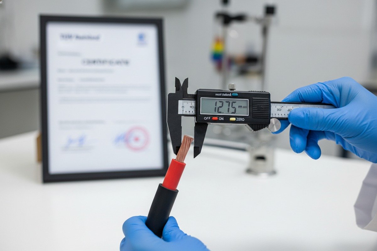
Every week, our quality control team sees cables returned because the outer jacket was just 0.3mm too thick for the MC4 gland. That tiny mismatch destroys the IP68 seal entirely XLPO (Cross-Linked Polyolefin) 3.
The MC4 connector's waterproof gland typically accepts cable outer diameters between 5.5mm and 8.0mm. Measure your cable's actual outer diameter with a digital caliper. If it falls outside this range, the rubber seal cannot compress properly, and your IP68 waterproof rating is compromised.

The waterproof gland inside an MC4 connector works by compressing a rubber gasket around the cable's outer jacket. If the cable is too thin, the gasket cannot grip. If the cable is too thick, the gland nut will not thread closed. Either way, moisture enters the connection and corrosion begins.
Why Outer Diameter Varies by Cable Standard
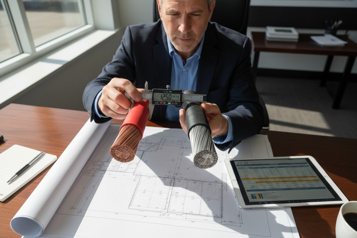
Different cable standards produce different outer diameters, even for the same conductor cross-section. A 4mm² H1Z2Z2-K cable 4 might have a 5.9mm outer diameter, while a 4mm² UL 4703 cable could measure 6.2mm. The difference comes from insulation thickness, jacket material, and manufacturing tolerances.
On our production lines, we measure outer diameter at multiple points along a drum to ensure consistency. A cable that varies by more than ±0.2mm along its length can cause intermittent seal failures in the field.
Outer Diameter Reference Table
| Cable Cross-Section | Typical Outer Diameter Range | MC4 Gland Compatibility |
|---|---|---|
| 2.5mm² (14 AWG) | 4.8–5.6mm | Requires small-bore MC4 gland insert |
| 4mm² (12 AWG) | 5.5–6.4mm | Standard MC4 gland — good fit |
| 6mm² (10 AWG) | 6.2–7.2mm | Standard MC4 gland — good fit |
| 10mm² (8 AWG) | 7.8–9.0mm | May exceed standard gland; use large-bore variant |
Practical Steps to Verify Fitment
First, request a cable sample before placing a bulk order. Use a digital caliper 5 at three points along a 1-meter section. Record the minimum and maximum readings. Then compare those readings to the MC4 connector's datasheet. Most reputable MC4 manufacturers like Stäubli publish the exact gland bore range.
Second, perform a trial assembly. Slide the gland nut and seal over the cable before crimping. If the seal slides freely without resistance, the cable is too thin. If you cannot push the cable through the seal at all, it is too thick. The correct fit should require moderate thumb pressure to push through.
Third, after assembly, perform a simple water spray test. Direct a garden hose at the connection for two minutes and check for moisture inside. This is a quick field-level check, not a replacement for formal IP68 testing, but it catches obvious failures.
Our engineers recommend always specifying the cable outer diameter tolerance in your purchase order. This single line item prevents the most common fitment issue we see in the field.
What specific certifications should I check to guarantee compatibility between my PV cables and connectors?
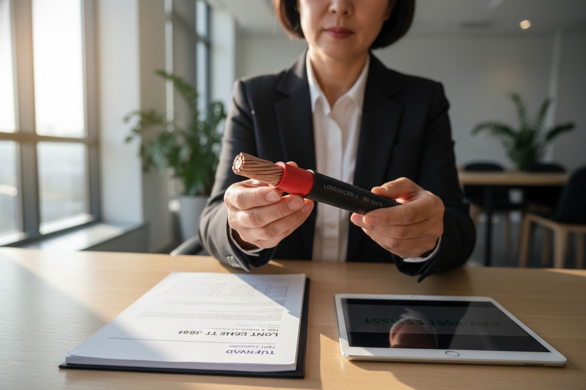
During a recent shipment to Germany, one of our distributor partners discovered that a competitor's cable carried a TÜV mark that had expired two years prior. The entire batch was rejected at customs, costing the buyer six weeks and a significant penalty.
Check for valid TÜV, UL (UL 6703 for connectors, UL 4703 for cables), and IEC 62852 certifications on both your cable and MC4 connector. These third-party certifications verify voltage ratings, current capacity, IP68 protection, and intermateability. Always cross-reference certificate numbers on the issuing body's online database.

Certifications are not just paperwork. They are proof that a product has been tested under controlled conditions and meets specific safety thresholds. In the solar PV industry, the consequences of fake or expired certifications include arc faults, fire, and rejected grid inspections.
Key Certifications Explained
TÜV (Germany): The gold standard for European solar components. TÜV Rheinland 6 and TÜV SÜD both test cables and connectors against EN 50618 and IEC 62852 7. A valid TÜV mark means the product passed flame, UV, and mechanical stress tests.
UL (United States/Canada): UL 4703 covers PV wire, and UL 6703 covers PV connectors. These certifications are mandatory for installations in the US and Canada. They verify voltage rating, wet insulation resistance, and flame propagation.
IEC 62852: This international standard specifically addresses PV connector intermateability. It defines the mechanical and electrical tests required to prove that a connector from one brand can safely mate with a connector from another brand.
Certification Comparison Table
| Certification | Scope | Key Tests | Required For |
|---|---|---|---|
| TÜV EN 50618 | PV cables | UV resistance, flame retardance, insulation integrity | European markets |
| UL 4703 | PV wire | Wet insulation resistance, cold bend, flame test | US and Canadian markets |
| UL 6703 | PV connectors | Temperature cycling, pull-out force, IP rating | US and Canadian markets |
| IEC 62852 | Connector intermateability | Mating force, contact resistance, IP68 under load | International projects |
| CPR (Dca/Cca) | Fire performance | Flame spread, heat release, smoke production | European building codes |
How to Spot Counterfeit Certifications
Counterfeit MC4 connectors are a growing problem. Here are practical ways to verify authenticity:
Look at the O-ring color. Genuine Stäubli MC4 connectors use black O-rings. Orange O-rings are a common indicator of non-Stäubli clones marketed as "MC4-compatible."
Check the certificate number. Every TÜV and UL certificate has a unique number. Go to the certifying body's website and search that number. If it does not exist or belongs to a different product, walk away.
Request the original test report. A legitimate manufacturer can provide the full test report, not just the certificate. Our team at Lonsoncable keeps all test reports on file and shares them with buyers on request. If a supplier hesitates to share test reports, that is a red flag.
NEC 2020 Section 690.33(C) and Brand Mixing
The US National Electrical Code now explicitly states that PV connectors must be mated only with connectors of the same brand and type unless intermateability has been certified per IEC 62852. NEC 2020 Section 690.33(C) 8 This rule exists because seal misalignment between brands can reduce IP ratings from IP68 to as low as IP44, inviting water damage and corrosion.
When sourcing from China for European or North American projects, always specify in your purchase contract that cables and connectors must carry matching, currently valid certifications for the target market.
How can I test the crimp quality to ensure a low-resistance connection for my solar project?
When we run crimp quality audits in our factory, roughly 1 in 50 hand-crimped samples from untrained workers fails the pull test. That failure rate is unacceptable for a 25-year solar installation.
Test crimp quality by measuring contact resistance with a micro-ohmmeter (target below 0.5 mΩ), performing a pull-out force test (minimum 50N for 4mm² cables), and conducting a visual inspection for exposed copper strands. Use dedicated MC4 crimping tools — never pliers — to achieve a gas-tight, low-resistance connection.

A bad crimp is the silent killer of solar systems. It may work fine during commissioning, but over months and years, micro-arcing at the loose contact point generates heat. That heat oxidizes the copper surface, which increases resistance further, which generates more heat. Eventually, the connector melts or catches fire.
The Three-Step Crimp Verification Process
Step 1: Visual Inspection. After crimping, look at the connection from all angles. The conductor strands should be fully enclosed within the crimp barrel. No individual strands should stick out. The insulation should end right at the crimp barrel's edge — not inside it, and not 5mm away from it.
Step 2: Pull Test. Grip the crimped contact in one hand and the cable in the other. Pull firmly. For a proper test, use a spring scale or force gauge. A 4mm² crimp should withstand at least 50N of pull force. A 6mm² crimp should handle 70N or more. If the cable slides out, the crimp die was wrong or the tool was not fully closed.
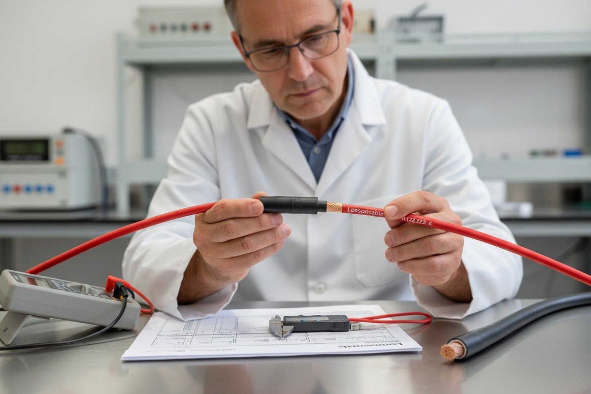
Step 3: Electrical Test. Use a micro-ohmmeter 9 or a quality multimeter set to the lowest resistance range. Place one probe on the crimped contact and the other on the bare conductor 100mm back from the crimp. A good crimp reads below 0.5 mΩ. Anything above 1.0 mΩ indicates a problem.
Common Crimp Failures and Their Causes
| Failure Type | Visual Sign | Root Cause | Field Consequence |
|---|---|---|---|
| Under-crimp | Contact can be pulled off by hand | Wrong die size or incomplete tool closure | High resistance, overheating |
| Over-crimp | Crushed conductor, deformed barrel | Excessive force or wrong die | Broken strands, eventual failure |
| Off-center crimp | Conductor visible on one side of barrel | Cable not seated properly before crimping | Uneven contact, intermittent connection |
| Insulation in barrel | Insulation caught inside crimp zone | Cable not stripped to correct length | No metal-to-metal contact |
Why Dedicated MC4 Crimping Tools Matter
Generic electrical crimping tools use different die profiles than MC4-specific tools. The MC4 crimp contact has a precise hexagonal or indent profile that requires a matched die. Using pliers or the wrong tool produces an oval crimp that looks adequate but fails under thermal cycling.
Our recommendation to all buyers: include a clause in your installation specifications that requires certified MC4 crimping tools on-site. This single requirement eliminates the majority of field crimp failures. When we supply cables for large EPC projects, we often include tool recommendations in the shipping documentation.
For incoming quality inspection at your warehouse, consider investing in a basic crimp cross-section analyzer. This tool cuts through a crimped sample and lets you view the conductor compression under magnification. It reveals voids and uncompressed strands that a pull test alone might miss.
Why is the insulation material of my solar cable critical for a long-term seal with MC4 connectors?
In our R&D lab, we run accelerated aging tests on every insulation compound we use. After simulating 15 years of UV exposure, some budget XLPO compounds shrank by over 3% — enough to break the MC4 gland seal entirely.
The insulation material determines your cable's outer diameter stability, UV resistance, and thermal expansion behavior over 25+ years. Cross-linked polyolefin (XLPO) and electron-beam cross-linked polyethylene (XLPE) maintain dimensional stability under UV and thermal cycling, ensuring the MC4 gland seal stays compressed and waterproof throughout the system's lifespan.

The MC4 connector's waterproof seal relies on constant pressure between the rubber gland gasket and the cable's outer jacket surface. If the insulation shrinks, hardens, or cracks over time, that pressure drops and the seal fails. This is why the insulation material is not just an electrical concern — it is a mechanical and environmental one.
How Insulation Materials Behave Over Time
XLPO (Cross-Linked Polyolefin): This is the standard insulation for H1Z2Z2-K and EN 50618 solar cables. It has excellent UV resistance, a wide operating temperature range (-40°C to +90°C), and low shrinkage rates. High-quality XLPO maintains its dimensions within 1% over 25 years of field exposure.
XLPE (Cross-Linked Polyethylene): Common in UL 4703 cables. XLPE offers strong dielectric performance and good thermal stability up to 120°C. However, some formulations are more susceptible to UV degradation without an outer jacket, so a UV-stabilized sheath is essential.
PVC (Polyvinyl Chloride): Sometimes used in budget cables, PVC is not suitable for long-term outdoor solar applications. It becomes brittle under UV exposure and can shrink significantly, breaking the MC4 gland seal within 3-5 years.
Thermal Expansion and Seal Integrity
Temperature swings cause cable insulation to expand and contract. This cyclical movement stresses the MC4 gland seal. Materials with high thermal expansion coefficients create more movement, leading to fatigue in the rubber gasket.
For projects in desert climates where daily temperature swings can exceed 50°C, selecting a low-expansion insulation material is critical. Our H1Z2Z2-K cables use an XLPO compound specifically formulated for low thermal expansion, which we verify through TMA (Thermomechanical Analysis) testing 10 during production.
Insulation Material Comparison
| Property | XLPO | XLPE | PVC |
|---|---|---|---|
| UV Resistance | Excellent | Good (with UV sheath) | Poor |
| Temperature Range | -40°C to +90°C | -40°C to +120°C | -10°C to +70°C |
| Thermal Expansion | Low | Medium | High |
| Dimensional Stability (25yr) | <1% change | 1-2% change | 3-8% change |
| Halogen-Free | Yes | Yes | No |
| MC4 Seal Longevity | Excellent | Good | Poor |
| Flame Retardancy | High | Medium | Medium (with additives) |
The Surface Finish Factor
Beyond dimensional stability, the surface texture of the cable jacket matters for the seal. A smooth, consistent jacket surface provides uniform contact with the MC4 gland gasket. Cables with rough, pitted, or inconsistent jacket surfaces — often a sign of poor extrusion control — create micro-channels where water can wick past the seal.
When evaluating cable samples from a new supplier, run your fingernail along the jacket surface. It should feel uniformly smooth. Any bumps, pits, or roughness suggest extrusion process issues that could compromise the seal.
At our Lonsoncable facility, we use laser-based surface profile scanners on our extrusion lines to maintain jacket smoothness within tight tolerances. This level of process control is what separates a cable that seals reliably for 25 years from one that starts leaking after five.
For buyers sourcing cables for harsh environments — coastal salt spray, desert UV, or tropical humidity — always request the insulation material's full datasheet, including accelerated aging test results. The material specification matters as much as the conductor specification when it comes to MC4 connector compatibility.
Conclusion
Verifying solar PV cable compatibility with MC4 connectors requires checking outer diameter fitment, certifications, crimp quality, and insulation material. Get these four factors right, and your connections stay safe for decades.
Footnotes
1. Found a step-by-step guide on MC4 connector assembly that details the cable gland and its function. ↩︎
2. Polycase provides a clear explanation of the IP68 rating based on IEC 60529 standard. ↩︎
3. SUNKEAN provides a comprehensive overview of XLPO cable insulation properties and applications. ↩︎
4. NPC Electric, a cable manufacturer, details the specifications and compliance of H1Z2Z2-K solar cables. ↩︎
5. MRC Lab explains what a digital caliper is and its use for accurate measurements. ↩︎
6. This is the official website for TÜV Rheinland, a leading international testing and certification body. ↩︎
7. This is the official page for the IEC 62852 standard from the International Electrotechnical Commission. ↩︎
8. Mayfield Renewables discusses the specific requirements of NEC 2020 Section 690.33(C) for PV connectors. ↩︎
9. Wuhan Musen Electric explains the principle and method of using a micro-ohmmeter for resistance testing. ↩︎
10. Covalent Metrology explains the working principle and applications of Thermomechanical Analysis (TMA) testing. ↩︎